AR6201 - RT6201 - RCU6201 - AR6203
DV 14307.03 Issue 1 09/2013 Page 2-5
2.3.3 RT6201 Installation
The RT6201 can be installed at a suitable place on the aircraft (for example
in avionics bay) or can be fixed using mounting kit MK6201-(010).
The mounting location for RT6201 shall be at least 30 cm away from the
aircraft magnetic compass, to avoid any interference to the magnetic compass
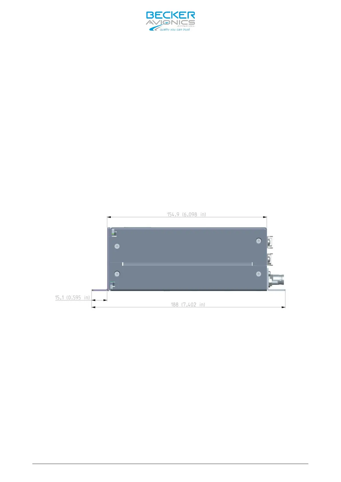
by the transceiver. For unit dimensions refer to Figure 2-8, Figure 2-9 and
Figure 2-10. Leave a clearance of minimum 5 mm between the RT6201 and other
avionics to allow air circulation. Forced cooling is usually not required.
Installation using RT6201 Mounting Holes
The required dimensions for installation using the mounting holes on the
RT6201 are given in Figure 2-9 (dedicated holes are marked with “M” letter).
Screws are included in the delivery.
Figure 2-8: RT6201 side view, dimensions in mm and (inches)