AR6201 - RT6201 - RCU6201 - AR6203
DV 14307.03 Issue 1 09/2013 Page 2-17
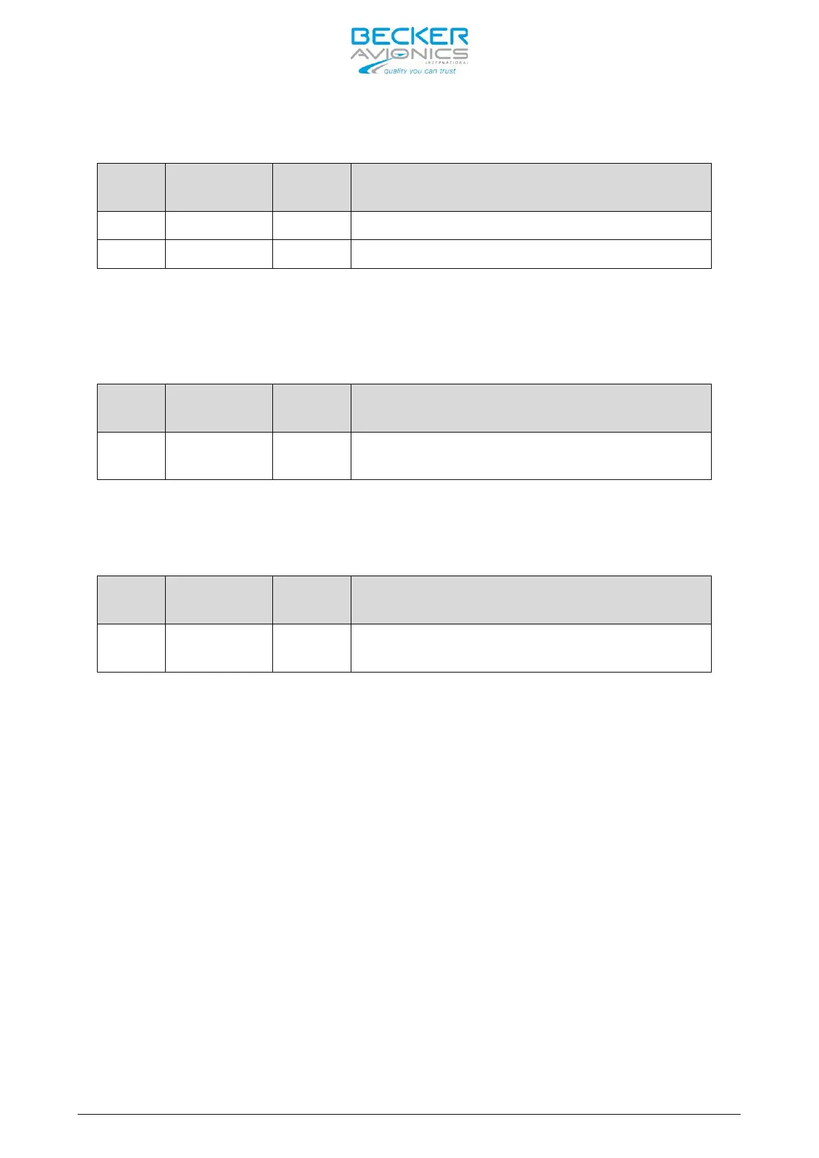
Panel Illumination
Pin No.
Pin Name
Directio
n
Function
P1-6 ILL_LO IN Illumination low input
P1-8 ILL_HI IN Illumination high input
The RCU6201 controller push-buttons and LCD display can be illuminated. The
illumination can be configured in the installation setup via front panel or
externally via pin P1-6/P1-8 For external configuration connect pin P1-6 to
system ground and pin P1-8 to dimming voltage bus.
External Power ON (/EXT_ON)
Pin No.
Pin Name
Directio
n
Function
P1-13 /EXT_ON IN/OUT
External Power ON input/output
ACTIVE state - closed contact to GND
The External Power “ON” input provides the possibility to power on the system
by ensuring this pin is earthed. This can be connected in installations with
a central avionics power switch or to power on RT6201.
External Exchange (/EXCH_CH)
Pin No.
Pin Name
Directio
n
Function
P1-15 /EXCH_CH IN
External “Exchange” key
ACTIVE state - closed contact to GND
The External “Exchange” input provides possibility to change active and
preset frequency or activate SCAN mode by means of momentary switch.
2.5 Installation and Configuration of 620X Transceivers
Connection to the following equipment is required as minimum for 620X VHF
transceivers:
• Power supply
• Antenna
• Microphone (direct or via external audio panel)
• Headphone or speaker (direct or via external audio panel)
• Push-To-Talk (PTT) switch
Note:
1. Use only cables which are qualified for aircraft use (self-
extinguishing).
2. Use AWG 20 for power supply and AWG 22/24 for other cables.
3. Fit sleeves over the solder joints on the equipment connector.
Crimp connectors are also available from BECKER.
4. Protect the power supply with a 7.5 A fuse.