AR6201 - RT6201 - RCU6201 - AR6203
DV 14307.03 Issue 1 09/2013 Page 2-59
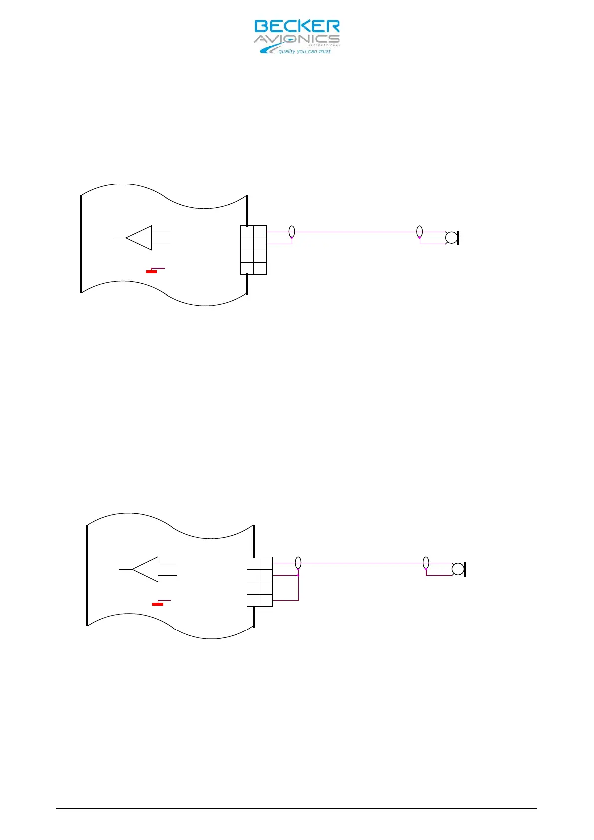
2.10.2 Dynamic Microphone Input
Retrofitting an AR4201 with the AR620X in a typical glider installation with
a dynamic microphone is shown below:
Dynamic Mike
18
6
5
8
MIKE_STD_LO
MIKE_DYN_LO
MIKE_STD_HI
6
5
MIKE_DYN_HI
8
18
Figure 2-30: AR6201 with wiring interface for AR4201
Connect the cable shielding to pin P1-6, which is the low side input for
dynamic microphone. Because in AR620X this input is balanced, the cable
shield is no longer connected to ground (unlike it was with the AR4201). In
most cases, it is not a problem.
If interference with the microphone signal does occur, it is recommended to
carry out the following modification:
Connect Pin P1-6 with Pin P1-8 (the cable shield is grounded). See figure
below.
Dynamic Mike
5
8
18
6
MIKE_STD_LO
MIKE_STD_HI
MIKE_DYN_LO
MIKE_DYN_HI
5
6
18
8
Figure 2-31: Modified dynamic microphone wiring interface for AR6201
2.10.3 Temperature Sensor
The AR620X has no temperature sensor input. Remove wire from pin P1-8 and pin
P1-20.
2.10.4 RS-232 Interface
The AR620X has no RS-232 interface for remote control. Remove wire from pin
P1-9 and pin P1-22.