AR6201 - RT6201 - RCU6201 - AR6203
Page 2-16 DV 14307.03 Issue 1 09/2013
2.4.3 Connector and Pin Assignment for RCU6201
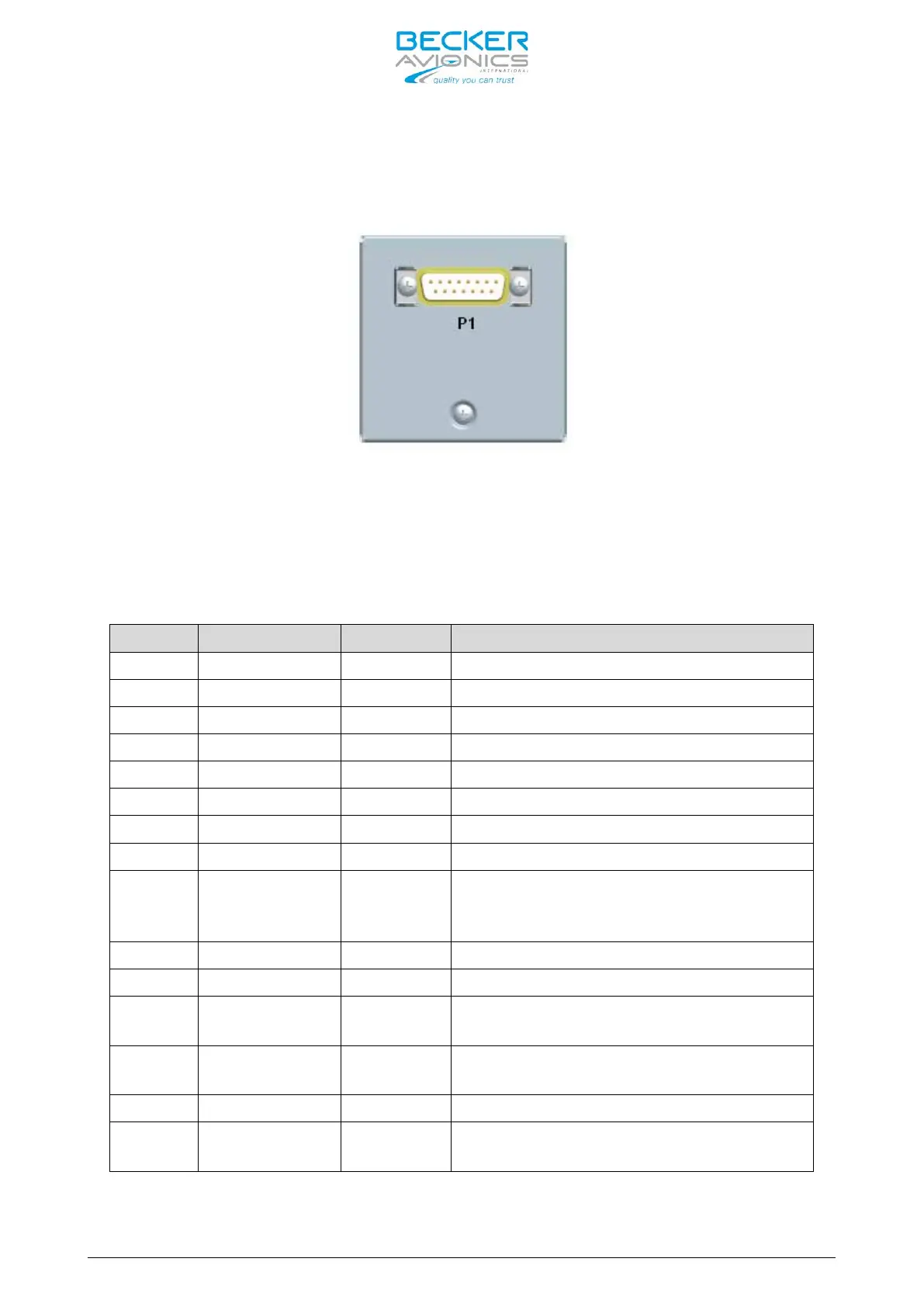
Figure 2-16: Connector on back plate of RCU6201
P1 Connector (System Interface) for RCU6201
The P1 connector (Figure 2-16) is a DSUB male connector with 15 pins and
slide-in fastener.
P1-1 TX0_422+ OUT Primary Control & Service Interface
Primary Control & Service Interface
Auxiliary Control Interface
Primary Control & Service Interface
Primary Control & Service Interface
Auxiliary Control Interface
P1-9 GND -
Power supply Ground (return),
shielding for RS422, Ground for
discrete lines
Auxiliary Control Interface
Power supply Hot (positive)
P1-12 /SRV_EN OUT
Service enable pin
ACTIVE state - closed contact to GND
P1-13 /EXT_ON IN
External Power ON input
ACTIVE state - closed contact to GND
Auxiliary Control Interface
P1-15 /EXCH_CH IN
External “Exchange” key
ACTIVE state - closed contact to GND