22 | VAS 6430 | Product descriptionen |
1 690 386 012 2013-09-24| Beissbarth GmbH
1
2
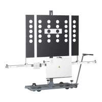
1 Spring sleeve
2 Return spring
4. Fit the spring sleeve with return spring in the dia.
20 hole of the adjustment beam.
1
2
3
Fig. 5: Fixing in position with locking bolt
1 Locking bolt
2 Teflon washer
3 Adjustment beam
i The Teflon washer provided must be positioned
between the underside of the beam and the
mounting clamp.
5. Attach the adjustment beam at the through-hole of
the mounting clamp.
6. Fix in position from above with the locking bolt.
"Adjustment device 6430/1
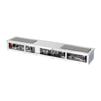
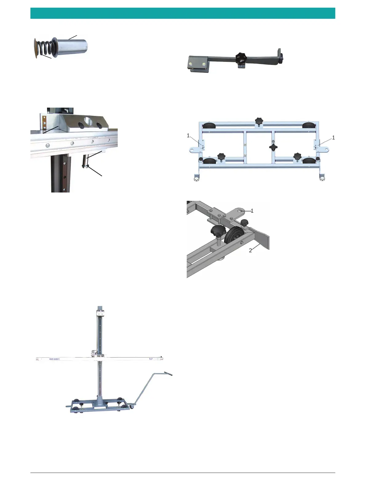
Fig. 6: Adjustment device 6430/1
Optional drive support
Fig. 7: Drive support
¶ Attach the drive support to the base frame on the
left and right using the two bolts.
Fig. 8: Drive support fitted
Fig. 9: Drive position
1 Hole for drawbar
2 Drive support extended
 Loading...