Technical data IRDH575
102
IRDH575_D00089_05_M_XXEN/01.2020
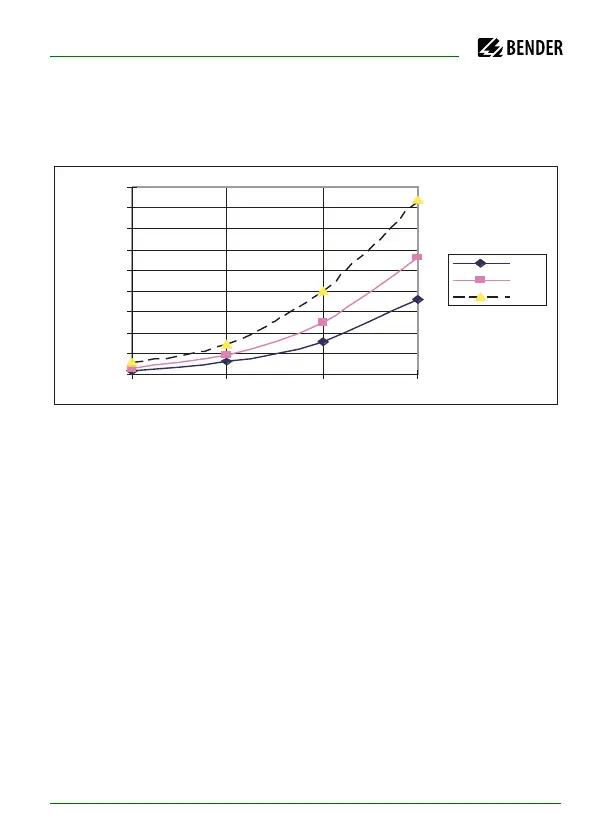
9.3.3 Characteristic curves for the insulation fault location
system EDS470
Allowable response values
Curve 1a:
Allowable response values in relation to the system voltage to be monitored
for a maximum system leakage capacitance C
e
as shown by curve 2a
In order to start automatic insulation fault location, the resistance values to be
selected for ALARM 1 and ALARM 2 must be sufficiently low at a given nominal
voltage. Otherwise, the EDS test current is not sufficient to localise the insula-
tion fault. Determine the suitable values by means of the characteristic curves.
0
5
10
15
20
25
30
35
40
45
24 48 110 230
U
n
(V)
R
F
(kW)
AC
3AC
DC