Operation and setting
40
IRDH575_D00089_05_M_XXEN/01.2020
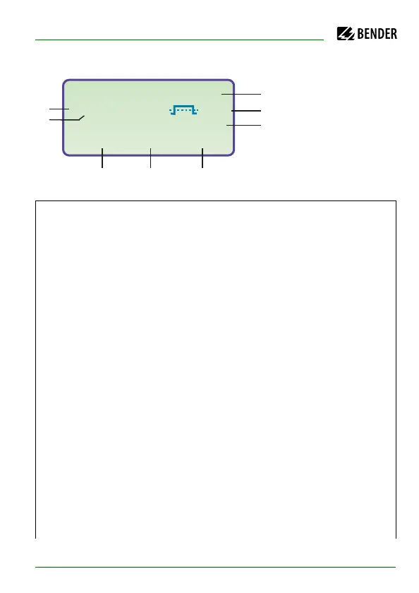
6.1.1 Display in case of active EDS and detected fault
1
Insulation resistance is indicated in kΩ
2
Additional information about the insulation resistance:
„+“: insulation fault at L+
„–“: insulation fault at L–
„s“: new measurement has started
3
Bus address of the active EDS4… (indication in case of fault detec-
tion)
4
Channel being monitored by the EDS4… (indication in case of fault
detection)
5
Test current in mA or µA (indication in case of fault detection) or
short = measuring input short-circuited
noCT = no CT connected
6
-on---auto: EDS is in the AUTO mode and just running. Further modes
are:
- on: EDS is activated
- off: EDS is deactivated
- pos470 : Addr. and channel of the EDS have to be selected
(in the Master mode only), EDS47… only
- 1cycle : after testing all the channels, once the EDS is deactivated
1
2
34 5
6
7
8
Insulation Fault
Rs=011k
W . H
--EDS:on---auto---
ADR:02 k03 12mA