80
IRDH575_D00089_05_M_XXEN/01.2020
7. Serial interfaces
7.1 RS-485 interface with BMS protocol
The RS-485 interface is galvanically isolated from the device electronics and
current output serves as a physical transmission medium for the BMS proto-
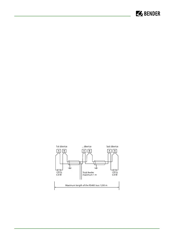
col. If several IRDH575 or other bus-capable devices are interconnected in a
network via the BMS bus, the BMS bus must be terminated at both ends with
a 120 Ω resistor. (Switch S1 = ON).
An RS-485 network that is not terminated, is likely to get instable and may re-
sult in malfunctions. Only the first and the last device in one line may be ter-
minated. Devices in between must not be terminated with 120 Ω
(switch S1 = OFF). Hence, stub feeders in the network must not be terminated.
The length of the stub feeders is restricted to 1 meter.