Function
23
IRDH575_D00089_05_M_XXEN/01.2020
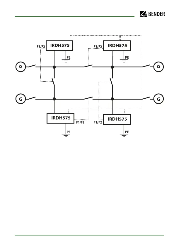
Example:
Let as assume, in the before-mentioned ring-type arrangement, the associa-
ted coupling switch of the Slave ISOMETER® 2 were open. The coupling swit-
ches of the BMS Master (Addr. 1) and of the Slaves 3 and 4 were closed. In this
case the ISOMETER® and EDS functions of the Master and the Slaves 3 and 4
would be deactivated. In spite of changing to the STANDBY mode, the Master
status of the device with address 1 would remain. That means, if a paramete-
rization is necessary, it has to be carried out via the IRDH575 with BMS
address 1.
BMS bus (A/B, RS485)
IT system 1
IT system 4 IT system 3
IT system 2
addr. 4 addr. 3
addr. 1 addr. 2