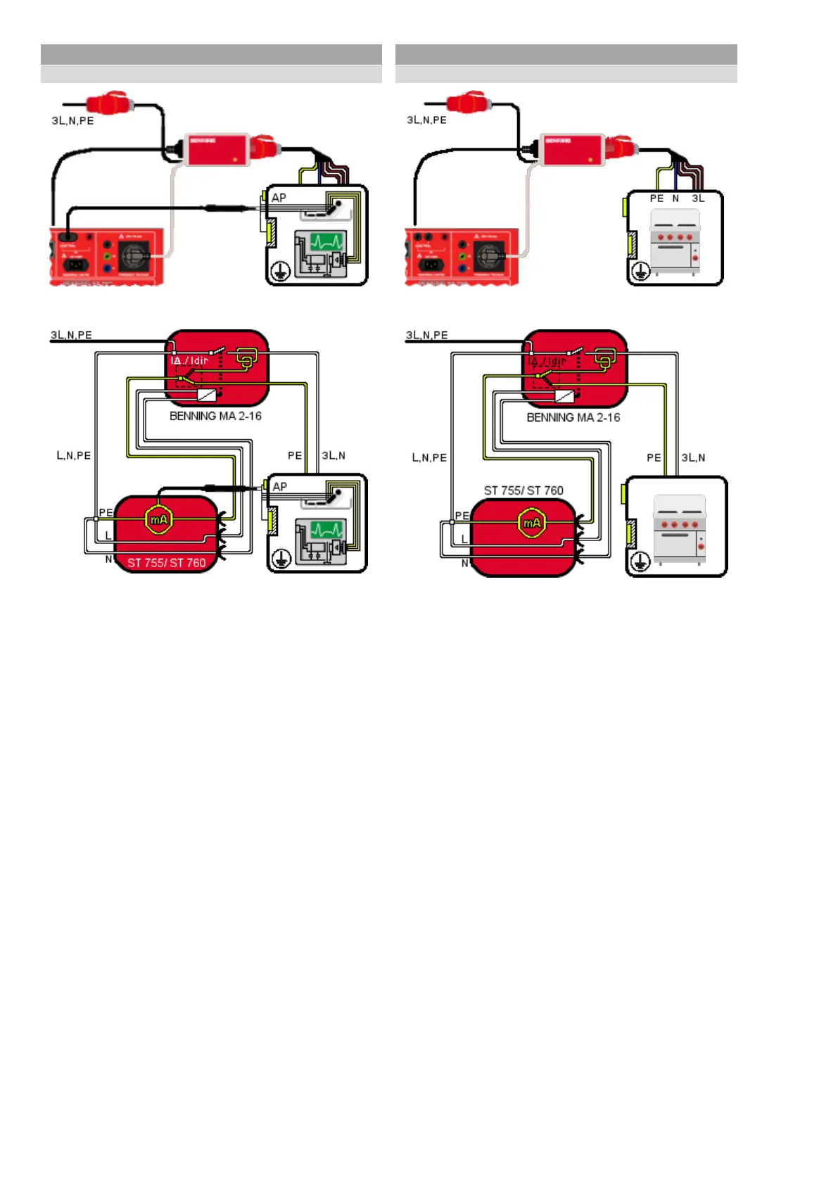
Class I, ILeak, with BENNING MA 2-16
Switch position of measuring adapter: IPE
dir.
Connection diagram
VDE 0751-1
Circuit diagram
VDE 0751-1
(switch position IPE direct)
Connect the BENNING MA 2-16 measuring adapter to the
BENNING ST 755/ ST 760 appliance tester according to the
connection conditions.
For differential current measurement, set the orange toggle switch
of the BENNING MA 2-16 to “IPE direct”.
Place the test sample onto an insulated surface.
Start the ILeak test at the appliance tester
(automatic test or manual test).
Follow the instructions shown on the display of the appliance
tester.
Class I, functional test, with BENNING MA 2-16
Switch position of measuring adapter: IPE
diff.
(IPE Δ)
Connection diagram
VDE 0701-0702, VDE 0751-1, VDE 0544-4
Circuit diagram
VDE 0701-0702, VDE 0751-1, VDE 0544-4
(switch position IPE Δ)
Connect the BENNING MA 2-16 measuring adapter to the
BENNING ST 755/ ST 760 appliance tester according to the
connection conditions.
For differential current measurement, set the orange toggle switch
of the BENNING MA 2-16 to “IPE Δ”.
Start the functional test at the appliance tester
(automatic test or manual test).
Follow the instructions shown on the display of the appliance
tester.
Within the framework of the functional test, it is not possible to
determine the values of the power and current consumption of the
test sample by means of the BENNING MA 2-16 measuring
adapter. The displayed values refer to the power consumption of
the BENNING MA 2-16 itself.