Ex 1) The drive determines the freq reference is lost when DRV- Frq is set
to 3 (Analog V1 input), I 16 to 1 and analog input signal is less than half the
value set in I 7.
Ex 2) The drive determines the freq reference is lost when DRV- Frq is set
to 6 (V1+I), I 16 to 2 and V1 input signal is either below the value set in I 7
or I input value is less than the I 12 value.
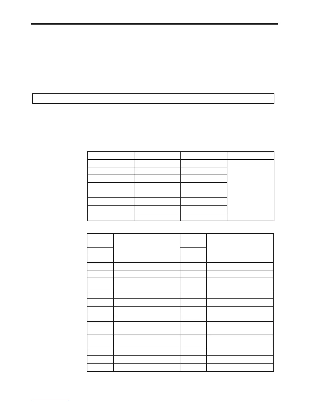
I17-I24: Multi-Function Input Terminals
Range: 0-24
Description: The multi-function input terminals can be defined for many different
applications. The following table shows the various programmable
functions.
114
6 - Parameter Descriptions
Setting
Range
Description
Setting
Range
Description
Display Display
0 Forward Run 13 -Reserved-
1 Reverse Run 14 -Reserved-
2 Stop Trip 15 Frequency (Up) Command
3 Reset [RST] 16
Frequency (Down)
Command
4 Jog Operation 17 3-wire operation
5 Step freq - Low 18 External trip: A (EtA)
6 Step freq - Mid 19 External trip: B (EtB)
7 Step freq - High 20 Self-diagnostic
8 Accel/Decel - Low 21
Exchange between PID
operation and V/F operation
9 Accel/Decel - Mid 22
Exchange between Option
and drive
10 Accel/Decel - High 23 Analog Hold
11 DC brake 24 Accel/Decel Disable
12 2nd motor
Code Display Default Setting
I17 P1 define 0
See table below
I18 P2 define 1
I19 P3 define 2
I20 P4 define 3
I21 P5 define 4
I22 P6 define 5
I23 P7 define 6
I24 P8 define 7
 Loading...

