Product Description BERGHOF Automation
32 DC1000_HB_en_2D0982003ZD00.doc 2VF100107FE03.doc
2.6. Mounting and Connection
2.6.1. Mounting
Required tools Box wrench, Allan key (7 mm) or open-end wrench SW
Securing The DIALOG CONTROLLER is equipped with approx. 15 mm-long, M 4,
welded-on stud bolts.
The unit is secured using U washers, spring washers/lock washers and nuts (M 4).
• Remove the shipping nuts and washers.
• Push the DIALOG CONTROLLER through the panel cutout.
• Secure the DIALOG CONTROLLER in the panel cutout.
• Adjust the DIALOG CONTROLLER in the panel cutout and tighten all nuts.
Disassembly:
Follow the reverse sequence to disassemble the DIALOG CONTROLLER.
2.6.2. Connections
Power supply Power for the DIALOG CONTROLLER comes from an external 24 VDC power
supply.
Before continuing with the connection, check that the external power supply meets
the required specifications.
External power supply (24 VDC)
Output voltage +24 VDC SELV (-15% / +20%)
Alternating component max. 5%
The direct voltage level may not fall below 20.4 V.
Power output Max. 2.0 A at +24 VDC at 25 °C
Installation All connections and wiring must be laid out to prevent any interference due to in-
ductive or capacitive pick-up from arising in the DIALOG CONTROLLER. The in-
feed lines must provide adequate current and voltage carrying capacity.
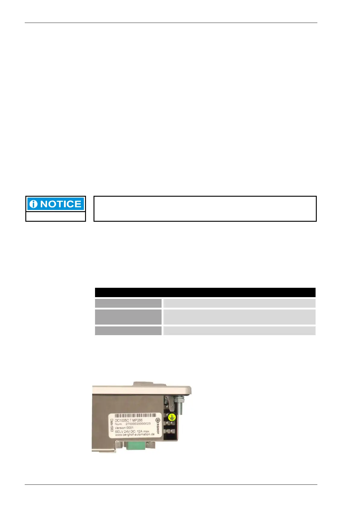
Ground
Connect the DIALOG CONTROLLER’s
housing to the ground lead (PE) with a
copper cross-section of at least 1.5 mm².
The DIALOG CONTROLLER is
equipped with a 6.3 x 0.8 mm plug-in tab
for this purpose.
2VF100236DG00.cdr
PE