Extension Modules BERGHOF Automation
64 DC1000_HB_en_2D0982003ZD00.doc 2VF100124FE01.doc
Digital inputs, positive switched
The digital inputs are positive-switching, type 1 inputs for 3-wire sensors. They are
designed for nominal 24 V input voltages. The inputs are transmitted to the CPU in
cycles. An open input is interpreted as being static 0 (LOW).
Impulse detection and interference suppression
Inputs are read in cycles. Impulses of < 100 µs are suppressed by the hardware.
The shortest possible sampling rate is 250 µs.
In order for impulses to be properly detected they must be longer than the sam-
pling rate defined by the software.
Multiple sampling can be programmed to suppress interference impulses. The
sampling rate and multiple sampling (filtering) can be activated in individual groups
of 32 inputs.
This function is only available for C applications. The sampling rate is predefined
under IEC 61131-3.
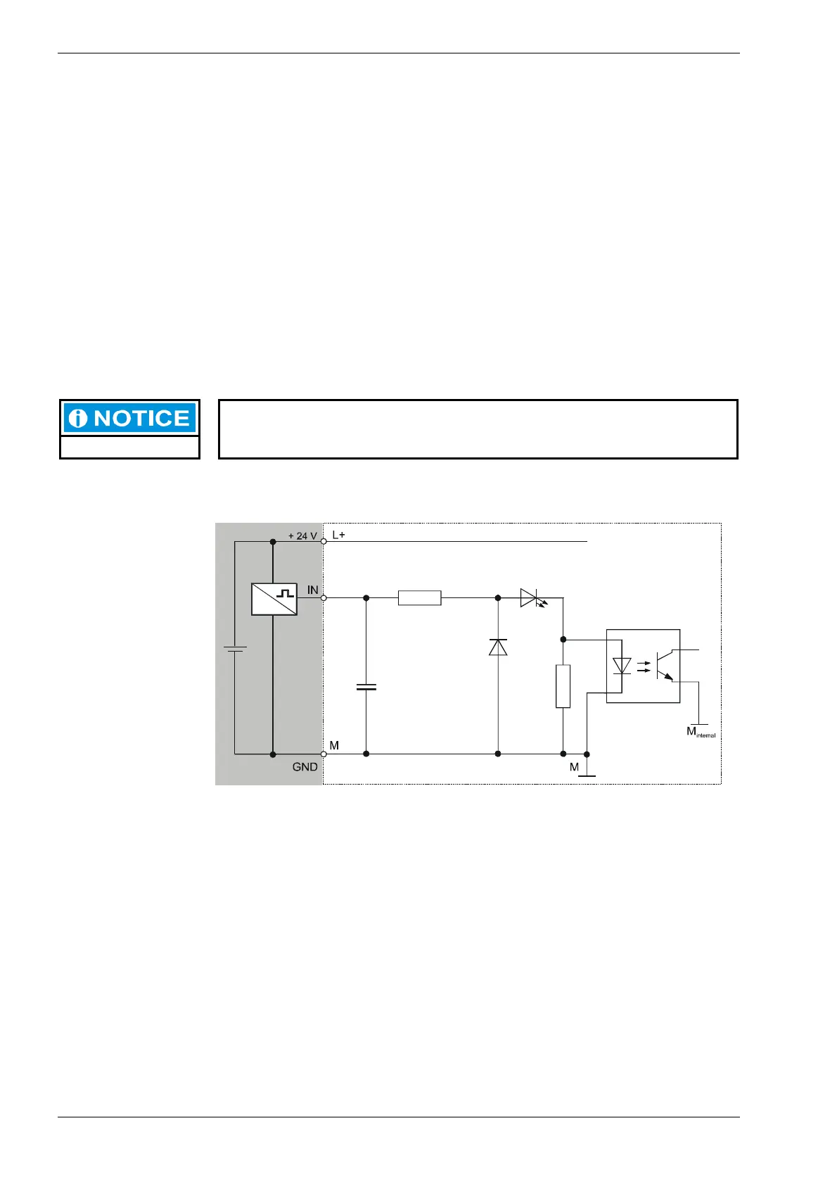
Basic input circuit diagram
2VF100009DG01.cdr