Extension Modules BERGHOF Automation
70 DC1000_HB_en_2D0982003ZD00.doc 2VF100124FE01.doc
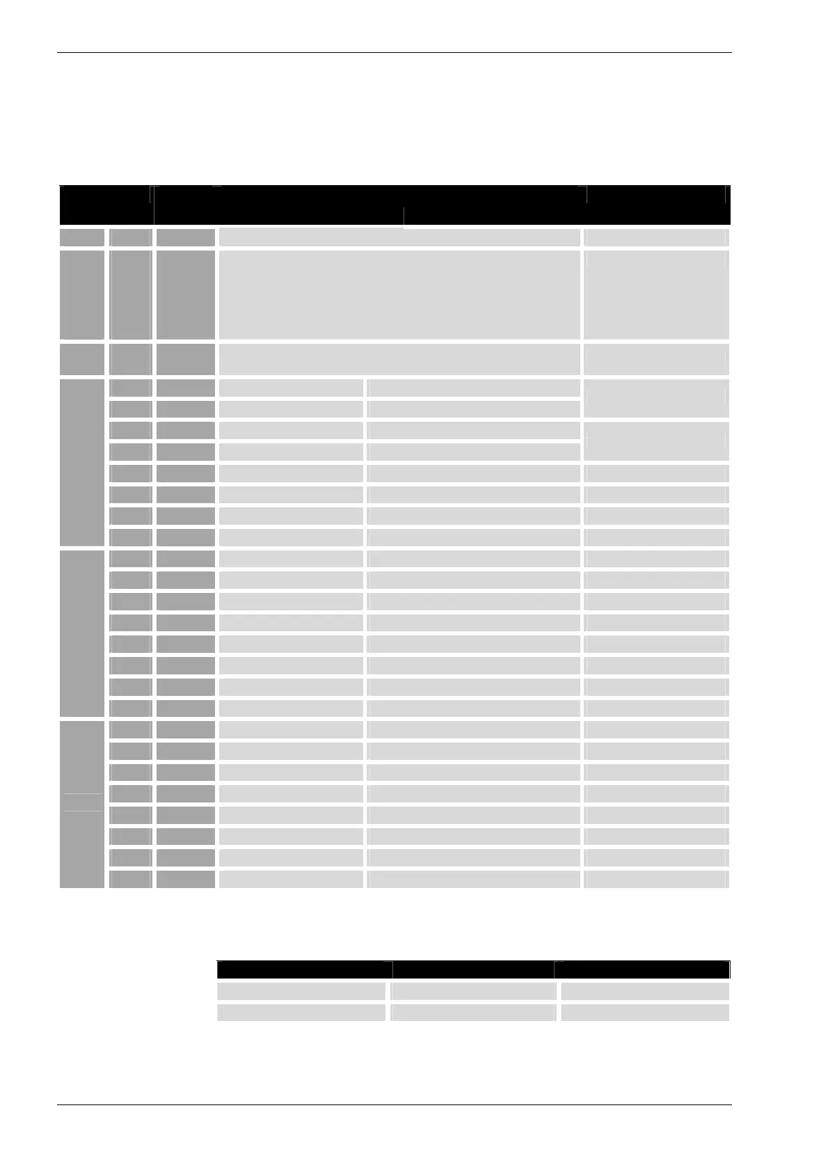
5.1.6. Digital Input/Output Pin Assignments
Configured as Connection
Signal
name
Digital I/O TPU- I/O
Note
X12 9 L1+ Feed
X12
X9
X7
X6
X1
X2
1..8
9
1..9
1..9
9
9
M1 GND for module and I/O feed
X4
X5
1..9
1..9
+24V= I/O feed Across L1+
1 IN1 Digital IN +24V Counter input, +24V
2 IN2 Digital IN +24V Counter input, +24V
Form encoder 1
3 IN3 Digital IN +24V Counter input, +24V
4 IN4 Digital IN +24V Counter input, +24V
Form encoder 2
5 IN5 Digital IN +24V
6 IN6 Digital IN +24V
7 IN7 Digital IN +24V
X1
8 IN8 Digital IN +24V
1 IN9 Digital IN +24V
2 IN10 Digital IN +24V
3 IN11 Digital IN +24V
4 IN12 Digital IN +24V
5 I/O13 Digital I/O +24V
6 I/O14 Digital I/O +24V
7 I/O15 Digital I/O +24V
X2
8 I/O16 Digital I/O +24V
1 OUT1 Digital OUT +24V
2 OUT2 Digital OUT +24V
3 OUT3 Digital OUT +24V
4 OUT4 Digital OUT +24V
5 OUT5 Digital OUT +24V
6 OUT6 Digital OUT +24V
7 OUT7 Digital OUT +24V
X9
8 OUT8 Digital OUT +24V
Encoder interface
Groups of 2 inputs can be combined to form a quadrature encoder for evaluation.
Function Input 1 Input 2
Encoder 1 IN 1 (X1) IN 2 (X1)
Encoder 2 IN 3 (X1) IN 4 (X1)
The encoder values are only reset (0) when the unit is switched on or rebooted af-
ter a reset.