BERGHOF Automation Extension Modules
2VF100124FE01.doc DC1000_HB_en_2D0982003ZD00.doc 67
5.1.5. Digital Outputs, Positive Switched
Voltages of >32 V and / or feed back can destroy the module.
This represents a fire hazard!
Each digital output can also be used as an input. When used as an input, the in-
formation provided under “Digital Inputs” applies.
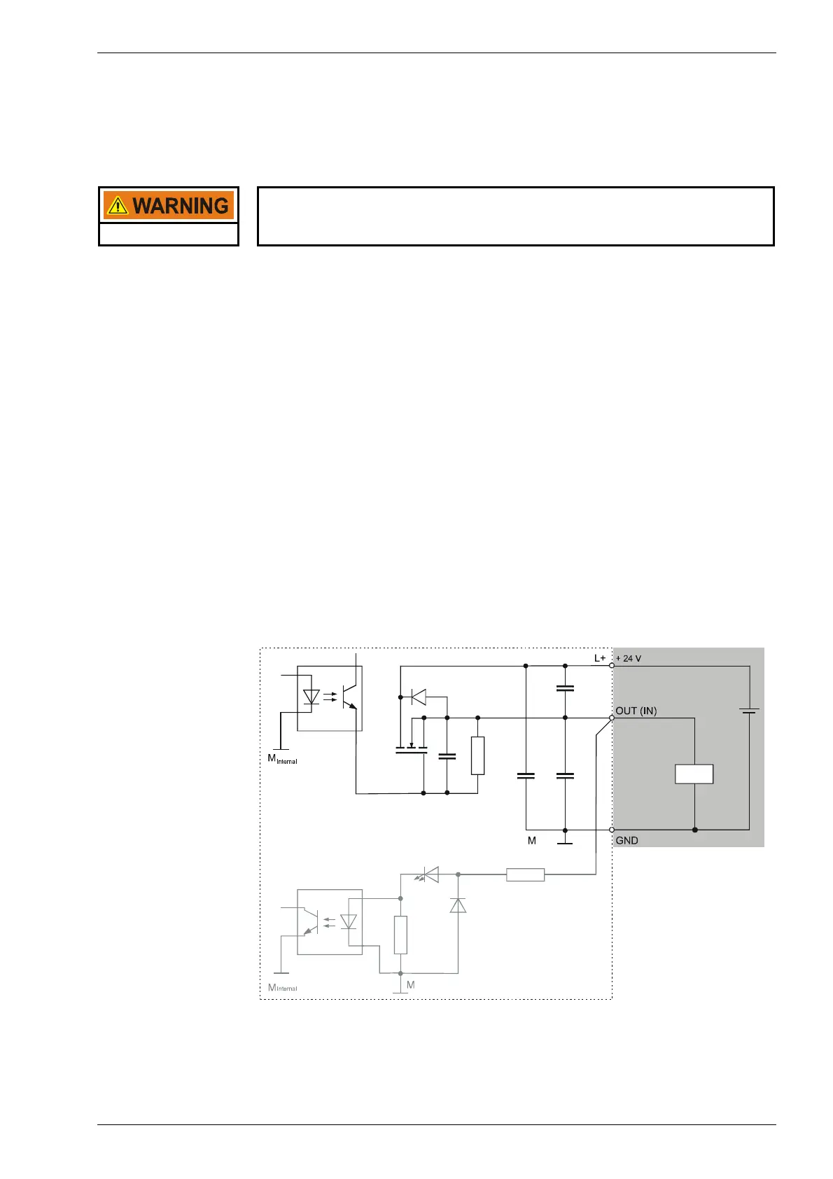
Outputs The outputs are positively switching 24 V outputs (2-wire). Output current: max.
500 mA per output. The outputs have a common reference potential (GND). Power
supply is separate from the module electronics supply (refer to “Pin Assignment”).
If there is no data connection to the CPU or if the internal module supply is inade-
quate the outputs independently switch to “0” (LOW).
Protected output All outputs are protected by an internal current limiter and thermal overload protec-
tion. In case of an overload, the current limiter switches the overloaded output off.
Once the overload has been corrected and the unit has cooled down the output
can be reactivated via the program. A quick deactivation using a terminal voltage of
50 V referenced to L+ protects all outputs against induced voltage peaks from in-
ductive loads.
If feedback or the quick deactivation produce thermal loads, the overload protec-
tion may also be prematurely tripped by uninvolved outputs.
Operating status The status of each output is indicated by a yellow status LED on the front of the
module. The LEDs are spatially assigned to the connection terminals. The LED is
on when the associated output is activated, that is, when it is logical “1” (HIGH).
Basic output circuit diagram
2VF100011DG01.cdr