Operation BERGHOF Automation
40 DC1000_HB_en_2D0982003ZD00.doc 2VF100108FE01.doc
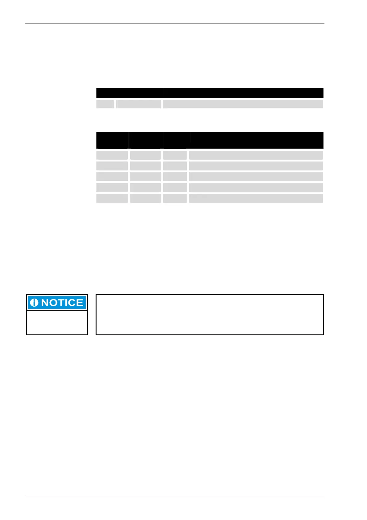
Status LED Four operating status LEDs provide information about the current status of the po-
wer supply, the module mode as well as fault and error messages.
LED Logical state
1 PWR (green)
ON = Correct supply voltage to the module electronics
Status LEDs for CP1131 programs
Status 3
(green)
Status 4
(red)
Status 5
(red)
Description
On Off Any Application program status: RUN
Off On Any Application program status: STOP
Off Flashing Any Application program status: ERROR STOP
Flashing On Any Application program status: Breakpoint STOP
Any Any On CP1131 mode: FORCE
Basic recovery procedure in case of an ERROR STOP:
• Determine the cause of the error; (indicated in the service menu on the display
or can be read using a web browser);
• Correct the cause of the error;
• Perform a controller reset, or alternatively:
Mode selection switch / Service menu / CoDeSys/ web browser;
• Return the controller to operation.
CP1131 FORCE mode:
FORCE indicates that the application program is running and CoDeSys forces a
value to be written to at least one variable at the start of every cycle. This makes
it evident to the user that the application program might react differently if no such
forced access to the PLC program’s process were to occur.
Status LEDs for CPC++ programs
LEDs 3 to 5 can each be separately controlled by application software.
Ethernet status LED Refer to the Section, “10/100 Base T Network Connection (Ethernet)”.