- 22 -
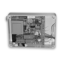
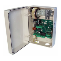
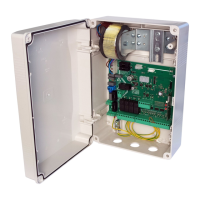
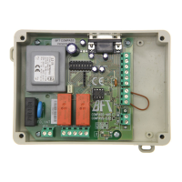
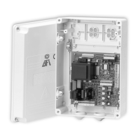
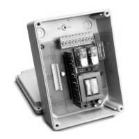
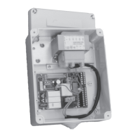
Control unit
EN
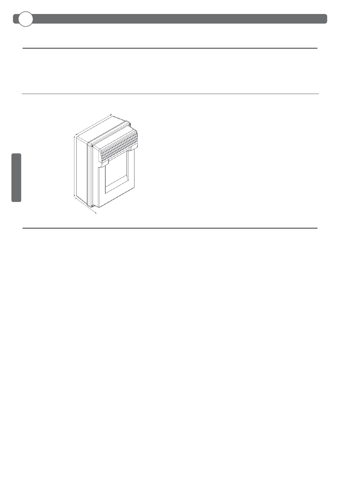
L = 200,05 mm
H= 275,50 mm
P= 126,08 mm
H
L
P
ENGLISH
3.1 CONTROL PANEL DIMENSIONS
3. TECHNICAL SPECIFICATIONS
- Power supply: 230Vac +-10%, 50/60Hz
- Motor output: 230Vac; 3A max
- Flashing light/tra c light: 230Vac; 40W
- Accessory output: 24Vac; 1A max
4. INSTALLATION SAFETY
In order to reach the level of safety required by current regulations, read the following prescriptions carefully.
1) Make all the connections in the terminal block after carefully reading the instructions given in this manual and observing the general
rules and technical standards governing electrical systems.
2) Upstream from the installation, t an omnipole miniature circuit breaker with a contact gap of at least 3 mm.
3) If there isn’t one already, install a residual current device with a threshold of 30 mA.
4) Check the e ectiveness of the grounding system and connect to it all the parts of the automation tted with a terminal or grounding
cable.
5) Fit at least one external warning device, such as a tra c light or ashing light, along with a warning or danger sign.
6) Fit all the safety devices required by the type of installation, taking into consideration the risks it can cause.
7) Separate the power lines (min. sect. 1.5 mm
2
) from the low-voltage signal lines (min. sect. 0,5 mm
2
) in the ducts.