March 2021
Installation, Operation and Maintenance Manual
MDE 254 Rev. 1
Wiring and Installation10
Section 6: Wiring and Installation
Section 6: Wiring and Installation
In general, the installation practice for HART communicating devices is the same as conventional
4 - 20 mA instrumentation. Individually shielded twisted pair cable, either in single-pair or multi-pair
varieties is the recommended wiring practice. Unshielded cables may be used for short distances if
ambient noise and cross-talk will not affect communication. The minimum conductor size is
0.51 mm diameter (#24 AWG) for cable runs less than 1,524 m (5,000 ft.) and 0.81 mm diameter
(#20 AWG) for longer distances.
6.1 Cable length
Most installations are well within the 3,000 m (10,000 ft.) theoretical limit for HART communication.
However, the electrical characteristics of the cable (mostly capacitance) and the combination of
connected devices can affect the maximum allowable cable length of a HART network. Table below
shows the effect of cable capacitance and the number of network devices on cable length. The table
is based on typical installations of HART devices in non-IS environments, i.e. no miscellaneous series
impedance. Detailed information for determining the maximum cable length for any HART network
configuration can be found in the HART Physical Layer Specifications.
Table 2.
N. network
devices
65 pF/m 95 pF/m 160 pF/m 225 pF/m
1 2,769 m 2,000 m 1,292 m 985 m
5 2,462 m 1,815 m 1,138 m 892 m
10 2,154 m 1,600 m 1,015 m 769 m
15 1,846 m 1,415 m 892 m 708 m
Recommended Minimum Conductor Size (Diameter):
• Below 1,785 m (5,000 ft.) total length: #24 AWG (0.51 mm diameter).
• Above 1,785 m (single pair) total length: #20 AWG (0.81 mm diameter).
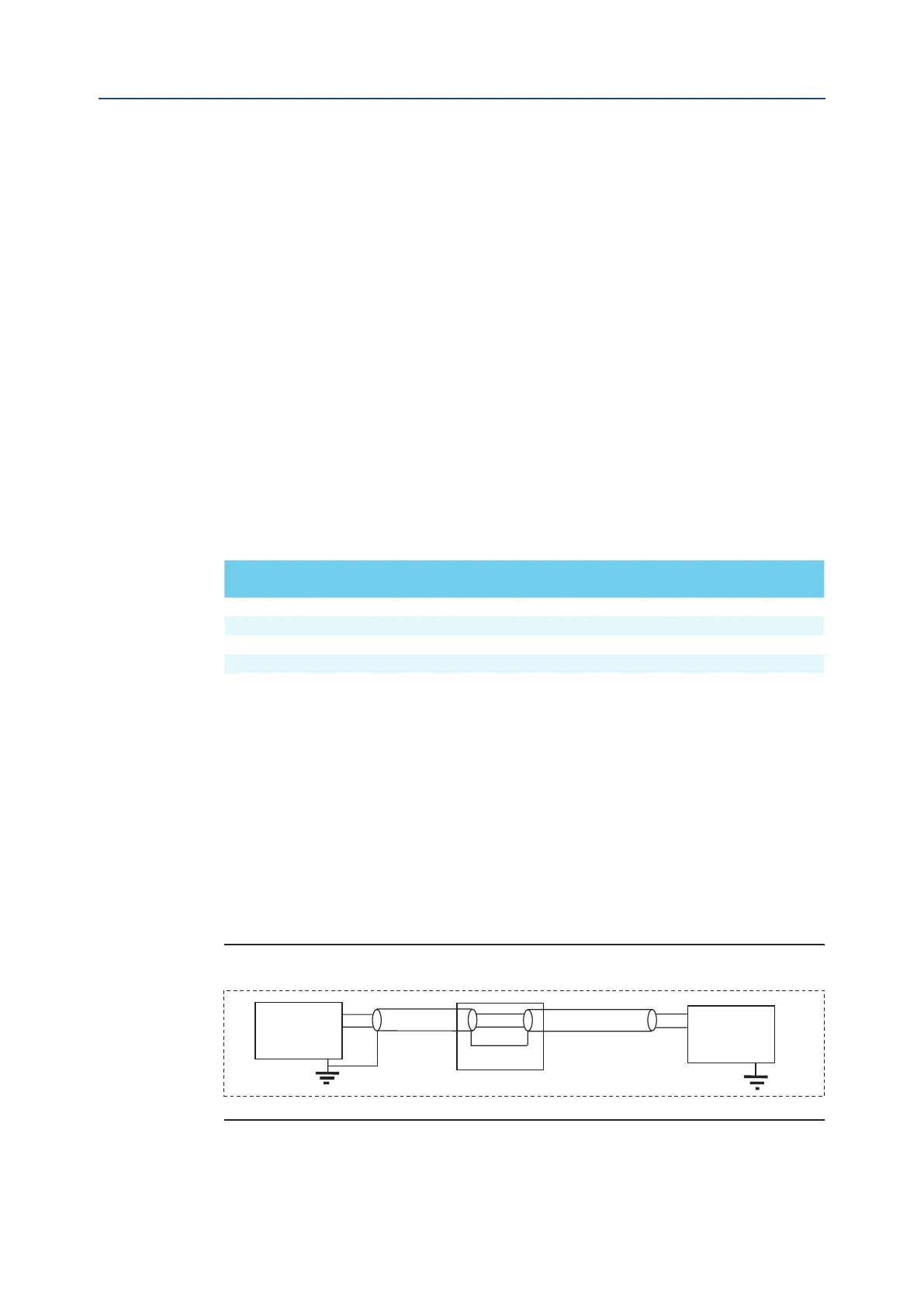
6.2 Shielding and Grounding
The cable shield must be grounded at one point only. This is usually done in the control room or near
to the source of the current loop. Ground connection may alternatively occur in a junction box or
other suitable location in the field area. The cable shield is usually left open at the field device.
Figure 7
Other grounding modes can be used if the coupling and the EMI do not damage the HART digital
signal. More information can be viewed on the HART FSK Physical Layer Specification.
4 - 20 mA
Current loop
source
Junction box
Field device
(actuator)
NOTE: Cable Capacitance – pF/m Cable Length – m