KB (E4 + E6) 02/2017 page 17/148
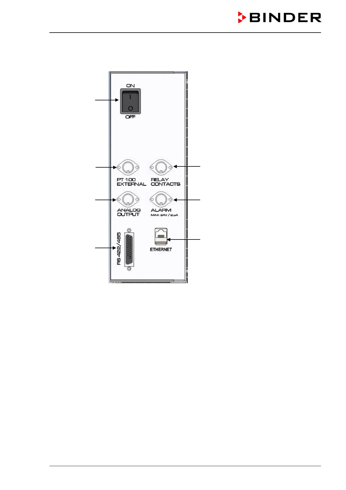
2.3 Lateral control panel with main power switch and optional equipment –
KB 240 / 400 / 720 (E6)
(1)
(2)
(3)
(4)
(5)
(6)
(7)
Figure 7: Lateral control panel at the right side of the refrigerating machine, with options
(1) Main power switch
(2) DIN-socket for additional Pt 100 temperature sensor (may be available via BINDER INDIVIDUAL
Customized Solutions)
(3) DIN socket for analog output 4-20 mA (option)
(4) RS422 interface (option)
(5) DIN-socket for zero-voltage relay control outputs (may be available via BINDER INDIVIDUAL Cus-
tomized Solutions)
(6) DIN-socket for zero-voltage relay alarm output (option)
(7) Ethernet interface for computer communication