KB (E4 + E6) 02/2017 page 115/148
19.6 Analog output for temperature (option)
With this option the chamber is equipped with an analog output 4-20 mA for temperature. This output
allows transmitting data to external data registration systems or devices.
The connection is realized as a DIN socket. A suitable DIN plug is enclosed.
With KB 53 / 115 (E4) the DIN (3) socket is located on the chamber rear:
With KB 240 / 400 / 720 (E6) the DIN socket (3) is located in the right lateral control panel.
ANALOG OUTPUT 4-20 mA DC
PIN 1: Temperature –
PIN 2: Temperature +
Temperature range: -10 °C / 14 °F to +100 °C / 212 °F
Figure 14: Pin configuration of the DIN socket (3)
19.7 Zero-voltage relay control outputs (may be available via BINDER
INDIVIDUAL Customized Solution)
The zero-voltage relay control outputs 1, 2 und 3 are used to switch any device connected via a DIN
socket on the chamber rear. They permit turning on and off individually the connected devices by the
controller. They can be programmed in fixed value entry mode (chap. 7.2) as well as in the time program
editor (chap. 9.3.7) or the week program editor (chap. 10.3.6) via the operation lines.
The connection is realized as a DIN socket. A suitable DIN plug is enclosed.
With KB 53 / 115 (E4) the DIN (5) socket is located on the chamber rear:
With KB 240 / 400 / 720 (E6) the DIN socket (5) is located in the right lateral control panel.
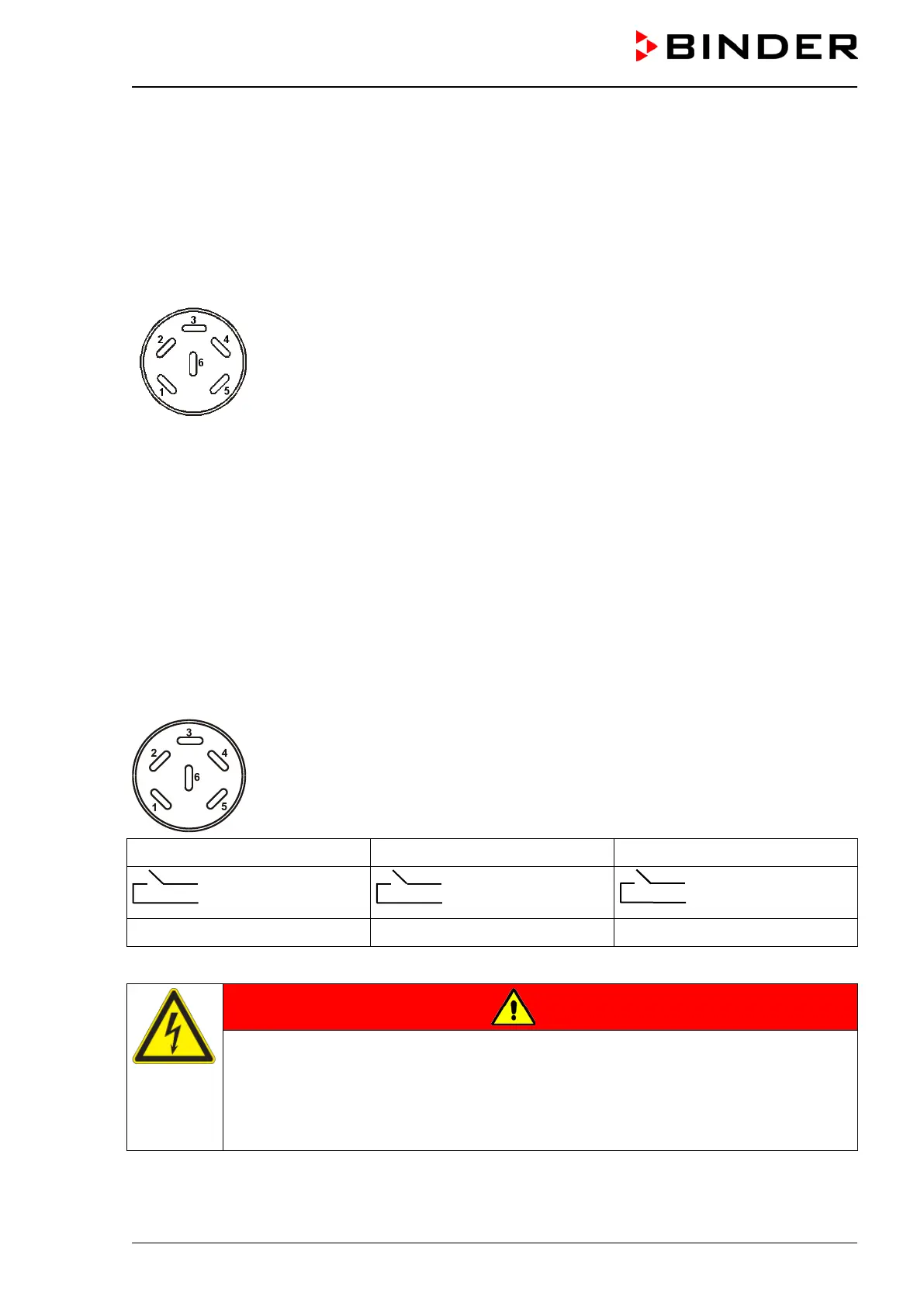
Figure 15: Pin configuration of the DIN socket (5)
Relay output 1 Relay output 2 Relay output 3
Pin 1: Pin
Pin 2: Make
Pin 3: Pin
Pin 4: Make
Pin 5: Pin
Pin 6: Make
Switching state On: 1xx Switching state On: x1x Switching state On: xx1
Maximum loading capacity of the switching contacts: 24V AC/DC – 2.5 A
DANGER
Electrical hazard.
Danger of death.
Damage to switching contacts and connection socket.
∅ Do NOT exceed the maximum switching load of 24V AC/DC – 2.5A.
∅ Do NOT connect any devices with a higher loading capacity.