KB (E4 + E6) 02/2017 page 2/148
Contents
1. SAFETY .................................................................................................................. 6
1.1 Legal considerations ........................................................................................................................... 6
1.2 Structure of the safety instructions ...................................................................................................... 6
1.2.1 Signal word panel ..................................................................................................................... 6
1.2.2 Safety alert symbol ................................................................................................................... 7
1.2.3 Pictograms ................................................................................................................................ 7
1.2.4 Word message panel structure ................................................................................................. 8
1.3 Localization / position of safety labels on the chamber ...................................................................... 8
1.4 Type plate............................................................................................................................................ 9
1.5 General safety instructions on installing and operating the chambers ............................................. 10
1.6 Intended use ..................................................................................................................................... 12
1.7 Operating instructions ....................................................................................................................... 12
1.8 Measures to prevent accidents ......................................................................................................... 13
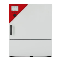
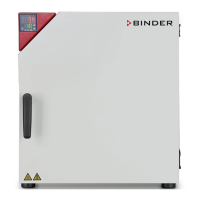
2. CHAMBER DESCRIPTION .................................................................................. 14
2.1 Chamber overview ............................................................................................................................ 15
2.2 Instrument panel ............................................................................................................................... 16
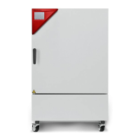
2.3 Lateral control panel with main power switch and optional equipment – KB 240 / 400 / 720 (E6) .. 17
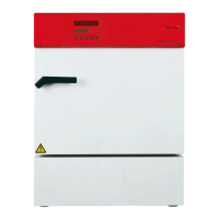
2.4 Chamber rear – KB 53 / 115 (E4) ..................................................................................................... 18
3. COMPLETENESS OF DELIVERY, TRANSPORTATION, STORAGE, AND
INSTALLATION .................................................................................................... 19
3.1 Unpacking, and checking equipment and completeness of delivery ................................................ 19
3.2 Guidelines for safe lifting and transportation ..................................................................................... 20
3.3 Storage .............................................................................................................................................. 20
3.4 Location of installation and ambient conditions ................................................................................ 21
4. INSTALLATION OF THE EQUIPMENT ............................................................... 22
4.1 Spacers for wall distance – KB 240 / 400 / 720 (E6) ........................................................................ 22
4.2 Mounting the flexible tilt protection kit – KB 400 (E6) ....................................................................... 23
4.3 Electrical connection ......................................................................................................................... 24
5. START UP ............................................................................................................ 25
6. FUNCTIONAL OVERVIEW OF THE T4.12 CHAMBER CONTROLLER ............. 25
6.1 Menu structure .................................................................................................................................. 26
6.1.1 General menu ......................................................................................................................... 26
6.1.2 Quick menu ............................................................................................................................. 28
6.1.3 “User” menu ............................................................................................................................ 28
6.2 Operating modes ............................................................................................................................... 29
6.2.1 Activating the “control off” mode or change to “fixed value” operating mode ......................... 29
6.3 Performance during and after power failure ...................................................................................... 31
6.4 Information ........................................................................................................................................ 32
7. CONFIGURATION OF OPTIONAL EQUIPMENT ................................................ 33
7.1 Turning on / off the optional interior socket ....................................................................................... 33
7.2 Switching on or off the optional zero-voltage relay control outputs .................................................. 34
7.3 Functional test of the optional alarm output ...................................................................................... 34
7.4 Switching on or off the optional object temperature display ............................................................. 35
7.5 RS 422 address (with optional RS 422 interface) ............................................................................. 35
8. SET-POINT ENTRY IN “FIXED VALUE” OPERATING MODE ........................... 36
8.1 Setting ranges: .................................................................................................................................. 36
8.2 Entering the set-points via “quick menu” ........................................................................................... 36
8.3 Entering the set-points via general menu ......................................................................................... 38