FlightHawk RF Test Set
A-14
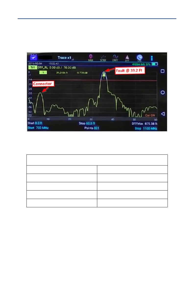
The graph below (Figure 1) shows a typical Fault Location measurement for an
antenna system.
Figure 1 Typical Fault Location Measurement
The table below (Table 3) shows typical component return loss.
Table 3. Typical Component Return Loss
Typical Component Return Loss
Antenna at Resonance -14 dB
Connector -25 dB
Jumper -35 dB
Lightning Protector -25 dB
Transmission Line -30 dB