16
sound, language, counter, etc. You can also view system
status and update software.
DEFAULT SETUP: Press to reset the oscilloscope’s settings to
the default factory configuration.
HELP: Enter the online help system.
AUTO: Automatically sets the oscilloscope controls to
produce a usable display of the input signals.
RUN/STOP: Continuously acquires waveforms or stops the
acquisition.
Note: If waveform acquisition is stopped (using the
RUN/STOP or SINGLE button), the TIME/DIV control expands
or compresses the waveform.
SINGLE: Acquire a single waveform and then stops waveform
acquisition.
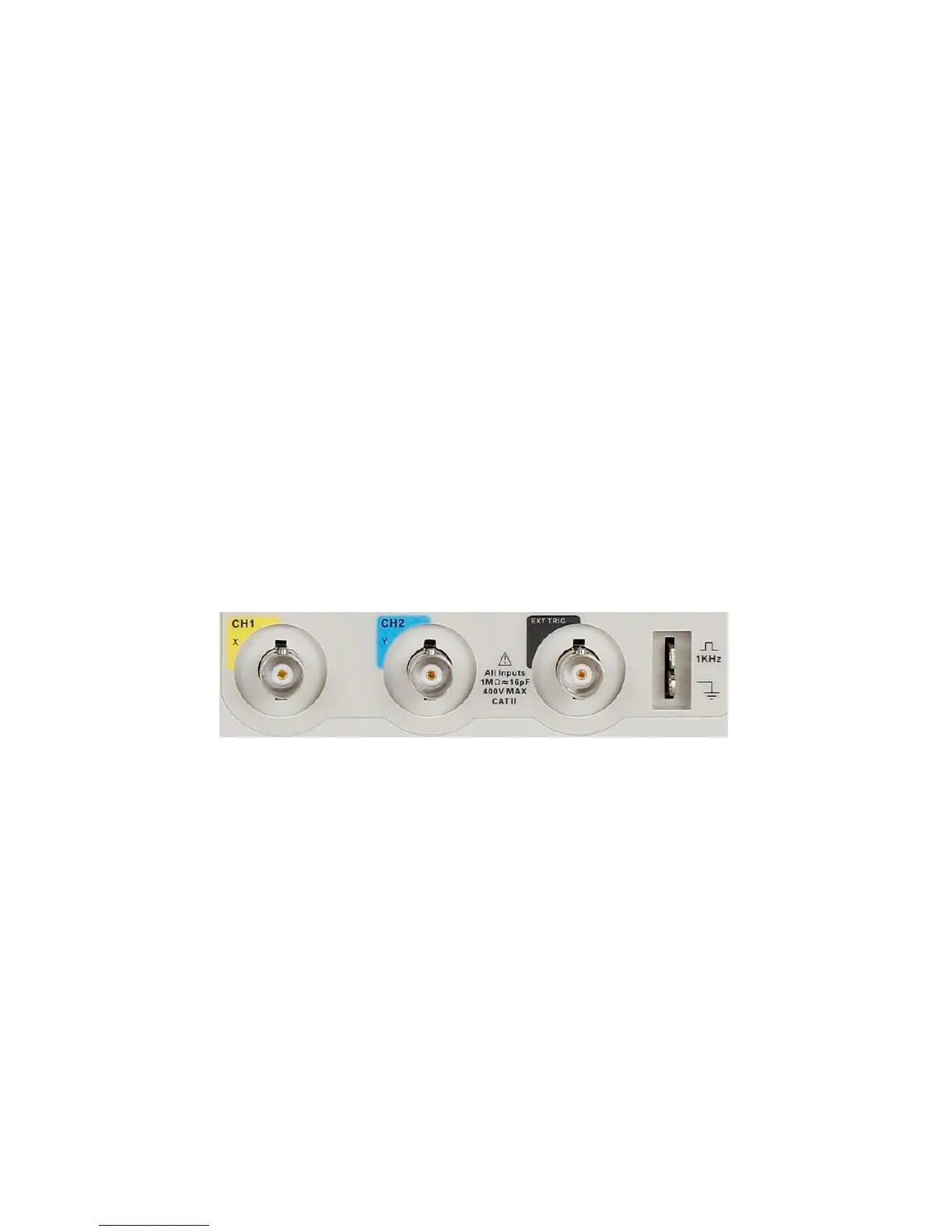
3.2 Connectors
Figure 3.2 – Connectors
Channel Connector (CH1, CH2): Input connectors for waveform
display.
EXT TRIG: Input connector for an external trigger source. Use the
Trigger Menu to select the “Ext” or “Ext/5” trigger source.
Probe Compensation: 1 kHz voltage probe compensation output
and ground. Use to electrically match the probe to the
oscilloscope input circuit.