16
1.8 7 7. 8 7 7. 2 2 6 9 BLACKBOX.COM
NEED HELP?
LEAVE THE TECH TO US
LIVE 24/7
TECHNICAL
SUPPORT
1.8 77.877.2269
CHAPTER 4: INVISAPC TRANSMITTERS
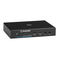
TABLE 4-1. INVISAPC TRANSMITTER COMPONENTS
NUMBER IN FIGURES 4-1
THROUGH 4-5
COMPONENT DESCRIPTION
1 Power LED Lights green when power is ON
2
(1) 2.5-mm barrel connector
for power
Links to 5-VDC external in-line power supply
3 (1) USB Type B connector Links to USB input source
4 (1) Link/Activity LED Lights green when there is activity on the link
5 (1) RJ-45 connector Links to 10-/100-/1000-Mbps network
6 (1) 10/100/1000-Mbps LED Lights green when data is being transmtted at 1000 Mbps
7 (1) DVI input connector
Links to DVI input source #1 on the single-head models (DTX1000-T and
DTX1000SA-T) and input source #2 on the dual-head model (DTX1002-T)
8 (1) DVI input connector Links to DVI input source #1 on the dual-head model (DTX1002-T)
9 (1) RJ-45 connector Links to RS-232 serial interface
10 (1) 3.5-mm connector Links to audio
11 (1) 3.5-mm connector Links to audio
The Transmitter uses Black Box’s compound compression algorithm for video called Dynamic Content Optimized Compression
(DCOC). This algorithm optimizes compression and latency on a frame-by-frame basis, depending on content in the video stream
and on available network bandwidth. This enables an optimal user experience in challenging network environments.
4.1 CONFIGURATION OF TRANSMITTER
The Transmitter is configured from an InvisaPC Receiver or Manager. The network settings, unit name, and video quality are among
the parameters that can be configured on a Transmitter.
Multiplatform support
The Transmitter is connected to the remote workstation via USB and DVI connectors. This enables the InvisaPC Receiver to
interoperate seamlessly with Windows, Linux
®
, and Macintosh
©
workstations/servers.


 To Next Page