29
1.8 7 7. 8 7 7. 2 2 6 9 BLACKBOX.COM
NEED HELP?
LEAVE THE TECH TO US
LIVE 24/7
TECHNICAL
SUPPORT
1.8 77.877.2269
CHAPTER 11: OPERATION OF INVISAPC SYSTEM
Operating a workstation through the InvisaPC system is no different than working directly connected to a PC desktop.
All peripherals operate as if directly connected, even though the workstation is located at a distance.
11.1 LED IDENTIFICATION
Front panel
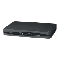
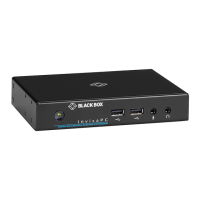
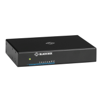
There is one LED on the front panel of an InvisaPC unit (integrated into the power-button on the Receiver and Manager) - called the
STATUS LED. The STATUS LED will light up when the unit (Receiver, Manager, or Transmitter) is turned on. The STATUS LED “blinks”
when a unit is being upgraded.
Rear panel
Two LEDs are built into the RJ-45 connectors on the InvisaPC Receiver, Manager and Transmitter. The definition of the operation of
these LEDs is shown in Table 11-1.
TABLE 11-1. RJ-45 CONNECTOR LEDS ON THE REAR PANEL
OF THE INVISAPC RECEIVER, MANAGER AND TRANSMITTER
LED STATUS DESCRIPTION
Activity
Green ON Linked OK
Green Flashing Transmit/Receive activity
Green OFF No Link
Link Speed
Blinks green one time 10 Mbps
Blinks green two times 100 Mbps
Blinks green three times 1000 Mbps
No blinking No valid link
11.2 ACCESSING THE SYSTEM
A connection is established using the OSD on an InvisaPC Receiver or Manager. Once you are connected, a series of messages will
be displayed on the screen to inform you of the progress of the connection. You will be able to interact with the remote workstation
as if it were located at your desk.
NOTE: If the remote workstation is powered off, the InvisaPC system will display a “black” screen for video when a connection
is made.


 To Next Page