19
1.8 7 7. 8 7 7. 2 2 6 9 BLACKBOX.COM
NEED HELP?
LEAVE THE TECH TO US
LIVE 24/7
TECHNICAL
SUPPORT
1.8 77.877.2269
CHAPTER 7: APPLICATION EXAMPLES
The InvisaPC system is built to be flexible so that it can be deployed in many different types of applications such as basic
extension, switching applications (sometimes called matrix), cloud-based desktops, control rooms, digital signage, and kiosk
applications and other applications in banking, financial services, broadcast, network operations, industrial, government and
enterprise computing sectors. InvisaPC provides the state-of-the art performance by:
using digital sources for video and audio, hence removing analog noise issues or other potential environmental issues
using advanced optimized compression to enable visually lossless video over standard low-bandwidth networks rather than a
proprietary connection or dedicated gigabit networks of many systems
7.1 VIDEO, AUDIO AND USB EXTENSION
Many applications require Video, Audio, or USB extension (or all three together) such as PC back-racking, board-room fit-out,
remote monitoring, and digital signage.
The InvisaPC system is setup to connect the Transmitter to the Receiver straight out of the box on a point-to-point network.
The Transmitter and Receiver can be attached to standard Ethernet IP networks to increase the distance between units – within
a building, between buildings, or across a country. Only standard Ethernet/IP rules and the maximum latency the application can
tolerate need to be considered. If video and/or audio extension only is being used, latency rarely is a consideration as the traffic is
typically one-way. When USB-based peripheral devices are also required a network latency of <50ms is recommended to avoid user
issues with “poor mouse response”, etc. For some applications, such as graphic design network latency ,<20ms may be required
to ensure user satisfaction. Latency normally is only an issue when extending across a WAN, because latency inside modern
buildings or on dedicated networks are much less than 1 ms.
In Figure 7-1, a typical deployment is shown in a basic extender application. In this deployment, only one Transmitter and Receiver
are used to allow remote access to a single workstation.
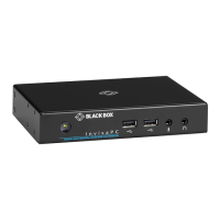
Transmitter
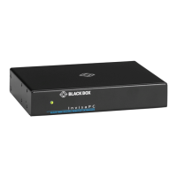
Receiver
FIGURE 7-1. BASIC EXTENDER APPLICATION


 To Next Page