Switch Settings
Switch 8 and 7 - Audio Selection
Switches 8 and 7 are represented as bits 1 and 0 respectively. This means that by setting
various on/off combinations of switches 8 and 7 you can select which SDI input is being used
for embedded audio in the HDMI and SDI multi view output signal.
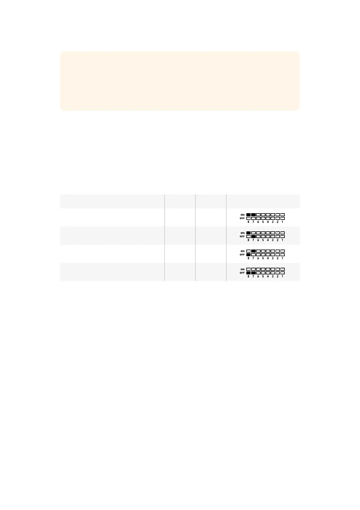
Audio Selection Table
Audio Source Switch 8 Switch 7 Switch Diagram
Input 1 ON ON
Input 2 ON OFF
Input 3 OFF ON
Input 4 OFF OFF
Switch 6 - Labels
Set switch 6 to ‘on’ to display labels for each window in your multi view output signal. These
labels can be set using Blackmagic MultiView setup as detailed later in this manual. Set switch 6
to ‘off’ to hide labels.
Switch 5 - Audio Meters
Set switch 5 to ‘on’ to display audio meters for each window in your multi view output signal. Set
switch 5 to ‘off’ to hide audio meters.
Switch 4 - Borders
Set switch 4 to ‘on’ to display borders between each MultiView window. Set switch 4 to ‘off’ to
hide borders.
Switch 2 and 1
Switches 2 and 1 are represented as bits 1 and 0 respectively. This means that by setting various
on/off combinations of switches 2 and 1 you can select the output format of your MultiView 4’s
SDI signal.
TIP Even though switch settings are printed on the base of your Blackmagic
MultiView 4, new features in later updates can add new settings so it’s worth
checking the latest version of this manual for the most up to date information.
You can download the latest version from the Blackmagic Design support
center at www.blackmagicdesign.com/support
2020Changing Settings using Switches