Installation
10
Leg Attachment
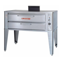
LEG VARIATIONS
Legs are available in 4” (101mm), 6” (152mm) or
25”(635mm) lengths orlowprofilecast ers.The6”
legs are used on the lower section of a double
stackedunit.The 4”legsmaybeusedwiththeop -
tional stands if additional height is required or
when mounting on a counter. The 25” legs are
used for a single oven located on the floor.
NOTE: For safety reasons, casters must not be
used with the 25” legs.
25I Adjustable Leg
4I Leg
6I Adjustable Leg
Low Profile Casters
Figure 6
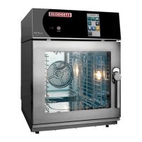
LEG ATTACHMENT
1. Align the threaded stud on one of the front
legs to the bolt hole located in the unit’s bot-
tomcorner.Turnthelegclockwiseandtighten
to the nearest full turn.
2. Align the leg plate holes with the bolt holes.
Secure with the two 1/2” bolts provided.
3. Repeat the above steps with the other front
leg. If lowprofilecastersareused,installthem
withthelockingcastersinthefrontoftheoven.
The rear casters do not lock. Ensure that the
locks are set on the front casters.
4. Tip the oven up on the newly installed front
legs. If casters are used, check that the locks
aresetonthefrontcasters.Repeat the above
steps for the rear legs.
5. Exceptforunitswithcasters, levelthe ovenby
screwing the adjustable feet in or out as nec-
essary.
Figure 7