•
THE
AUTOMATIC TRANSMISSION
POWER FLOW DIAGRAMS (MECHANICAL)
Fa
•
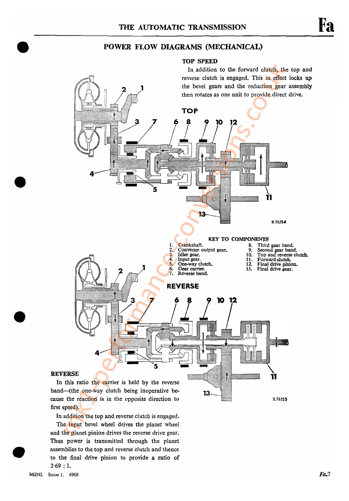
TOP
SPEED
In addition to the forward clutch, the top and
reverse clutch
is
engaged. This in effect locks
up
the bevel gears and the reduction gear assembly
then rotates as one unit to provide direct drive.
4
8.767S"
REVERSE
Fa.7
B.707SS
•
11
KEY
TO
COMPONENTS
8.
Third gear band.
9. Second gear band.
10.
Top
and reverse clutch.
11. Forwardclutch.
12. Final drive pinion.
13. Final drive gear.
13
1.
Crankshaft.
2. Converter output gear.
3. Idler gear.
4.
Input
gear.
5. One-way clutch.
6. Gear carrier.
7. Reverse band.
REVERSE
In this ratio the carrier
is
held by the reverse
band-(the
one-way clutch being inoperative be-
cause the reaction
is
in the opposite direction to
first speed).
In addition the top and reverse clutch
is
engaged.
The input bevel wheel drives the planet wheel
and the planet pinion drives the reverse drive gear.
Thus power
is
transmitted through the planet
assemblies to the top and reverse clutch and thence
to the final drive pinion to provide a ratio
of
2·69 :
1.
MINI.
Issue
1.
4908
•
•
mk1-performance-conversions.co.uk