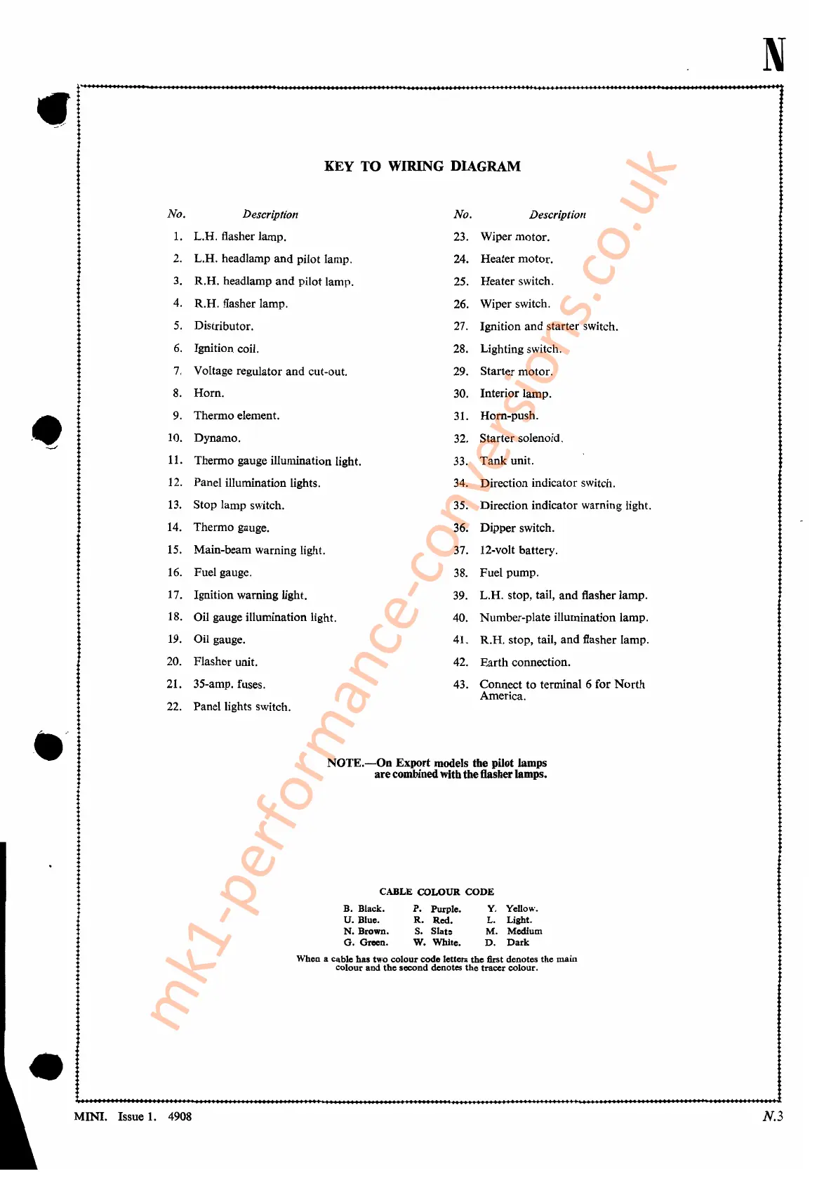
KEY TO WIRING DIAGRAM
No.
Description
No.
Description
1.
L.H. flasher lamp.
23.
Wiper motor.
2.
L.H. headlamp and pilot lamp.
24.
Heater motor.
3.
R.H. headlamp and pilot lamp.
25.
Heater switch.
4.
R.H. flasher lamp.
26.
Wiper switch.
5.
Distributor.
27.
Ignition and starter switch.
6.
Ignition coil.
28.
Lighting switch.
7.
Voltage regulator and cut-out.
29.
Starter motor.
8.
Horn.
30.
Interior lamp.
••
9.
Thermo element.
31.
Horn-push.
10. Dynamo.
32.
Starter solenoid.
::.../
11.
Thermo gauge illumination light.
33.
Tank
unit.
12.
Panel illumination lights.
34.
Direction indicator switch.
13.
Stop lamp switch.
35.
Direction indicator warning light.
14.
Thermo gauge.
36.
Dipper switch.
15.
Main-beam warning light.
37.
12-volt battery.
16.
Fuel gauge.
38.
Fuel pump.
17.
Ignition warning light.
39.
L.H. stop, tail, and flasher lamp.
18.
Oil gauge illumination light.
40.
Number-plate illumination lamp.
19.
Oil gauge.
41.
R.H. stop, tail, and flasher lamp.
20.
Flasher unit.
42.
Earth connection.
21.
35-amp. fuses.
43.
Connect to terminal 6 for
North
America.
22.
Panel lights switch.
NOTE.-On
Export
models the pilot lamps
are
combinedwith theflasher lamps.
CABLE
COLOUR
CODE
B. Black.
P.
Purple. Y. Yellow.
U.
Blue.
R.
Red.
L.
Light.
N.
Brown. S.
Slat:
M. Medium
G.
Green. W. White.
D.
Dark
When a cable has two colour code letters
the
first denotes the main
colour and
the
second denotes the tracer colour.
N
•
MINI. Issue
1.
4908
N.3
mk1-performance-conversions.co.uk