THE
STEERING
•
•
•
•
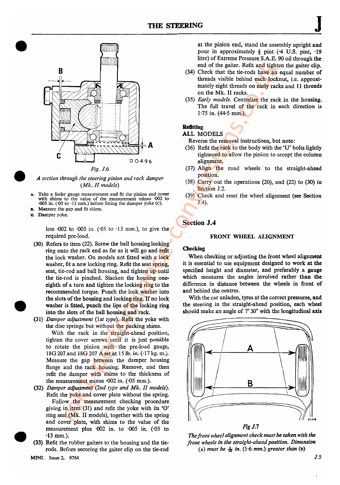
Fig. J.6
A.
section through the steering pinion and rack damper
(Mk.
11
models)
A..
Take a feeler gauge measurement and fit the pinion end cover
with shims to the value
of
the measurement minus ·002
to
·005 in. (,05 to '13 mm.) before fitting the damper yoke (c).
s. Maasure the gap and fit shims.
Co
Damper
yoke.
less ·002 to ·005 in. (,05 to
·13
mm.), to
give
the
required pre-Ioad.
(30)
Refers to item (22). Screw the ball housing locking
ring onto the rack end as far as it will go and refit
the lock washer. On models not fitted with a lock
washer, fit a new locking ring. Refit the seat spring,
seat, tie-rod and ball housing, and tighten up until
the tie-rod
is
pinched. Slacken the housing one-
eighth
of
a turn and tighten the locking ring to the
recommended torque. Punch the lock washer into
the slots
of
the housing and locking ring.
If
no lock
washer is
fitted, punch the lips
of
the locking ring
into the slots
of
the ball housing and rack.
(31)
Damperadjustment
(Ist
type). Refit the yoke with
the disc springs but without the packing shims.
With the rack in the straight-ahead position,
tighten the cover screws until
it
is
just possible
to rotate the pinion with the pre-Ioad gauge,
18G207 and 18G207 A set
at
15
lb. in. (,17
kg.
m.).
Measure the gap between the damper housing
flange and the rack housing. Remove, and then
refit the damper with shims to the thickness
of
the measurement minus ·002 in. (,05 mm.).
(32) Damper adjustment (2nd type and
Mk.
11
models).
Refit the yoke and cover plate without the spring.
Follow the measurement checking procedure
giving in item
(31)
and refit the yoke with its
'0'
ring seal (Mk.
II
models), together with the spring
and cover plate, with shims to the value
of
the
measurement plus
·002 in. to ·005 in. (,05 to
·13 mm.).
(33)
Refit the rubber gaiters to the housing and the tie-
rods. Before securing the gaiter clip on the tie-rod
MINI. Issue 2. 9764
J
at
the pinion end, stand the assembly upright and
pour in approximately
t pint (·4 D.S. pint, ·19
litre)
of
Extreme Pressure S.A.E.
90
oil throughthe
end
of
the gaiter. Refit
and
tighten the gaiter clip.
(34) Check that the tie-rods have
an
equal number
or
threads visible behind each locknut, i.e. approxi-
mately eight threads on early racks and
11
threads
on the Mk.
11
racks.
(35) Early models. Centralize the rack
in
the housing.
The full travel
of
the rack in each direction is
I
·75
in.
(44·5
mm.).
Refitting
ALL MODELS
Reverse the removal instructions, but note:
(36)
Refit the rack to the body with the 'u' bolts lightly
tightened to allow the pinion to accept the column
alignment.
(37)
Align the road wheels to the straight-ahead
position.
(38)
Carry out the operations (20), and (22) to (30) in
Section J.2.
(39)
Check and reset the wheel alignment (see Section
JA).
Section
J.4
FRONT
WHEEL
ALIGNMENT
Checking
When checking
or
adjusting the front wheel alignment
it
is
essential to use equipment designed to work
at
the
specified height and diameter, and preferably a gauge
which measures the angles involved rather than the
difference in distance between the wheels in front
of
and behind the centres.
With the car unladen, tyres
at
the correct pressures, and
the steering in the straight-ahead position, each wheel
should make an angle
of
7'
30"
with the longitudinal axis
A
B
FigJ.7
The
front
wheelalignment check
must
be taken with the
front
wheels in the straight-aheadposition. Dimension
(A)
must
be
-«
in. (1·6
mm.)
greater than
(B)
J.5
mk1-performance-conversions.co.uk