THE
ENGINE
•
•
(8)
Use Service tools 18G 304 with adaptor set
18G 304 N (cadmium-plated) to remove the
fly-
wheel.
NOTE.-The
black screws from set 18G
304
M
must not be used on the diaphragm clutch.
(9) Screw the three adaptor screws into the flywheel
and fit the plate
of
tool 18G
304
over the screws
with the retaining nuts screwed on evenly to keep
the plate parallel with the flywheel.
(10) Screw the centre bolt
of
adaptor set 18G
304
N
through the plate
of
tool 18G
304.
Hold the
fly-
wheel from turning and tighten the centre bolt
against the flywheel retaining screw until the
fly-
wheel
is
released from the crankshaft taper.
(11) Unscrew
and
remove the flywheel retaining screw
and keyed washer and withdraw the flywheel.
Inspecting
(12) Inspect the cover for elongation
of
the driving pin
holes. .
(13)
Inspect the driving pins for ridging and wear; fit
three new pins
if
any are worn.
(14)
Inspect the driving straps; fit three new ones
if
any
are worn.
A
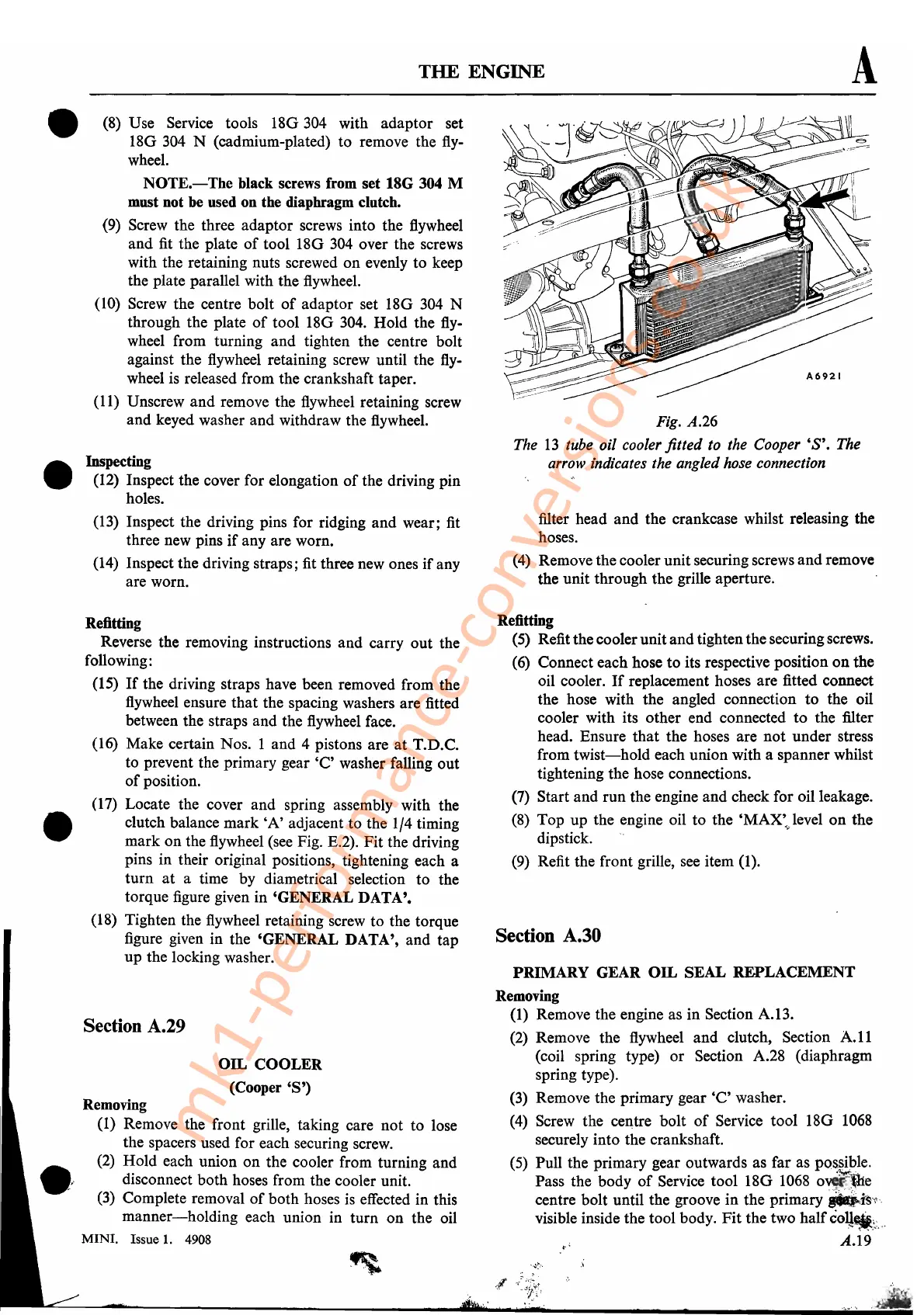
Fig. A.26
The
13
tube oil cooler fitted to the
Cooper'S'.
The
arrow indicates the angled hose connection
filter head and the crankcase whilst releasing the
hoses.
(4)
Remove the cooler unit securing screws and remove
the unit through the grille aperture.
•
Refitting
Reverse the removing instructions and carry out the
following:
(15)
If
the driving straps have been removed from the
flywheel ensure that the spacing washers are fitted
between the straps and the flywheel face.
(16) Make certain Nos. 1 and 4 pistons are
at
T.D.C.
to prevent the primary gear
'e' washer falling out
of
position.
(17)
Locate the cover and spring assembly with the
clutch balance mark
'A'
adjacent to the 1/4 timing
mark on the flywheel (see Fig. E.2). Fit the driving
pins in their original positions, tightening each a
turn
at
a time by diametrical selection to the
torque figure given in 'GENERAL DATA'.
(18) Tighten the flywheel retaining screw to the torque
figure given in the 'GENERAL DATA', and tap
up the locking washer.
Section A.29
OIL
COOLER
(Cooper'S')
Removing
(1) Remove the front grille, taking care not to lose
the spacers used for each securing screw.
(2)
Hold each union on the cooler from turning and
disconnect both hoses from the cooler unit.
(3)
Complete removal
of
both hoses
is
effected in this
manner-holding
each union in turn on the oil
MINI. Issue
1.
4908
Refitting
(5)
Refit the coolerunit andtighten the securing screws.
(6)
Connect each hose
to
its respective position
on
the
oil cooler.
If
replacement hoses are fitted connect
the hose with the angled connection
to
the oil
cooler with its other end connected to the filter
head. Ensure that the hoses are not under stress
from
twist-hold
each union with a spanner whilst
tightening the hose connections.
(7)
Start and run the engine and check for oil leakage.
(8)
Top up the engine oil to the
'MAX'!evel
on
the
dipstick. "
(9)
Refit the front grille, see item (1).
Section A.30
PRIMARY GEAR
OIL
SEAL REPLACEMENT
Removing
(1) Remove the engine as in Section A.13.
(2)
Remove the flywheel and clutch, Section
A.ll
(coil spring type) or Section A.28 (diaphragm
spring type).
(3)
Remove the primary gear
'C'
washer.
(4)
Screw the centre bolt
of
Service tool 18G
1068
securely into the crankshaft.
(5)
Pull the primary gear outwards as far as possible.
Pass the body
of
Service tool 18G
1068
ov~e
centre bolt until the groove in the
primary_Js~\
visible inside the tool body.
Fit
the two half
co~~\:
..
:
,.'
A.19
mk1-performance-conversions.co.uk