A
THE
ENGINE
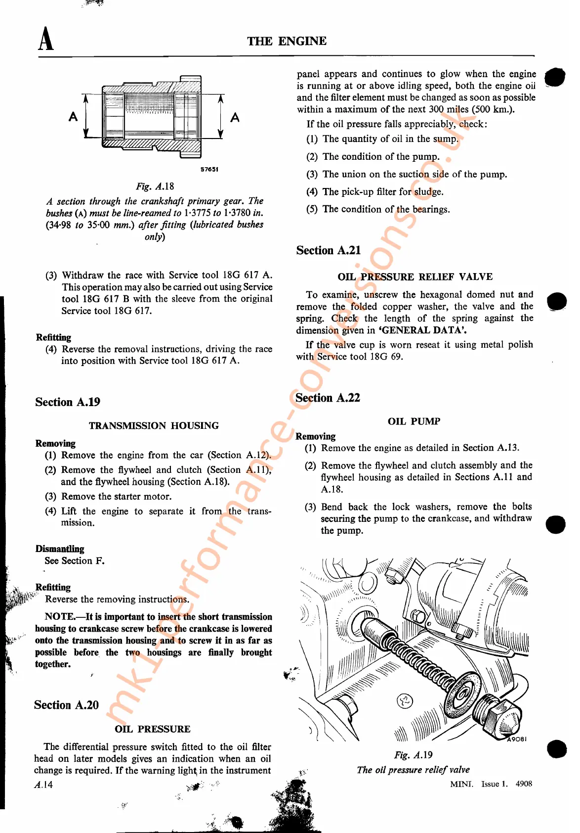
Fig. A.I8
A section through the crankshaft primary gear. The
bushes
(A)
must be line-reamed to
1·3775
to
1·3780
in.
(34·98 to 35·00 mm.) after fitting (lubricated bushes
only)
A
57651
A
panel appears and continues to glow when the engine •
is
running
at
or
above idling speed, both the engine oil
.~",'
and the filter element must be changed as soon as possible
within a maximum
of
the next 300 miles (500 km.).
If
the oil pressure falls appreciably, check:
(1)
The quantity
of
oil in the sump.
(2)
The condition
of
the pump.
(3)
The union
on
the suction side
of
the pump.
(4)
The pick-up filter for sludge.
(5)
The condition
of
the bearings.
Section A.21
(3)
Withdraw the race with Service tool 18G
617
A.
This operationmay also
be
carried outusing Service
tool 18G
617
B with the sleeve from the original
Service tool 18G
617.
Refitting
(4)
Reverse the removal instructions, driving the race
into position with Service tool 18G
617
A.
OIL
PRESSURE RELIEF VALVE
To examine, unscrew the hexagonal domed nut and •
remove the folded copper washer, the valve and the
--=_
spring. Check the length
of
the spring against the
dimension given in 'GENERAL DATA'.
If
the valve cup is worn reseat it using metal polish
with Service tool 18G
69.
Section A.19
Section A.22
TRANSMISSION HOUSING
Removing
(1)
Remove the engine from the car (Section A.12).
(2)
Remove the flywheel and clutch (Section
A.ll),
and the flywheel housing (Section A.I8).
(3)
Remove the starter motor.
(4)
Lift the engine to separate it from the trans-
mission.
OIL
PUMP
Removing
(1)
Remove the engine as detailed in Section A.13.
(2)
Remove the
flywheel
and clutch assembly and the
flywheel
housing as detailed in Sections
A.11
and
A.I8.
(3)
Bend back the lock washers, remove the bolts
securing the pump to the crankcase, and withdraw
•.
,
the pump.
OIL
PRESSURE
•
Fig. A.I9
The oil pressure relief valve
MINI. Issue
1.
4908
Dismantling
See
Section F.
The differential pressure switch fitted to the oil filter
head
on
later models gives an indication when an oil
change
is
required.
If
the warning
ligh~
in the instrument
A.14
Section A.20
J,.~~
VI'
~efitting
l'"~~rW~·l'
Reverse the removing instructions.
NOTE.-It
is
important to insert the short transmission
housing to crankcase screw before the crankcase is lowered
onto the transmission housing and to screw
it
in as far as
possible
before,
the
two
housings are finally brought
together.
mk1-performance-conversions.co.uk