Removing
(1) Remove the engine (Section A.12), the rocker shaft
assembly (Section A.5), the push-rods and tappets
(Section A.9), and the distributor (Section A.I0).
(2)
Unscrew the camshaft locating plate
and
withdraw
the camshaft.
(3)
If
the camshaft bearings are worn, remove the
flywheel housing and transmission case (Sections
A.18 and A.19).
•
THE
ENGINE
Section A.23
CAMSHAFT
A
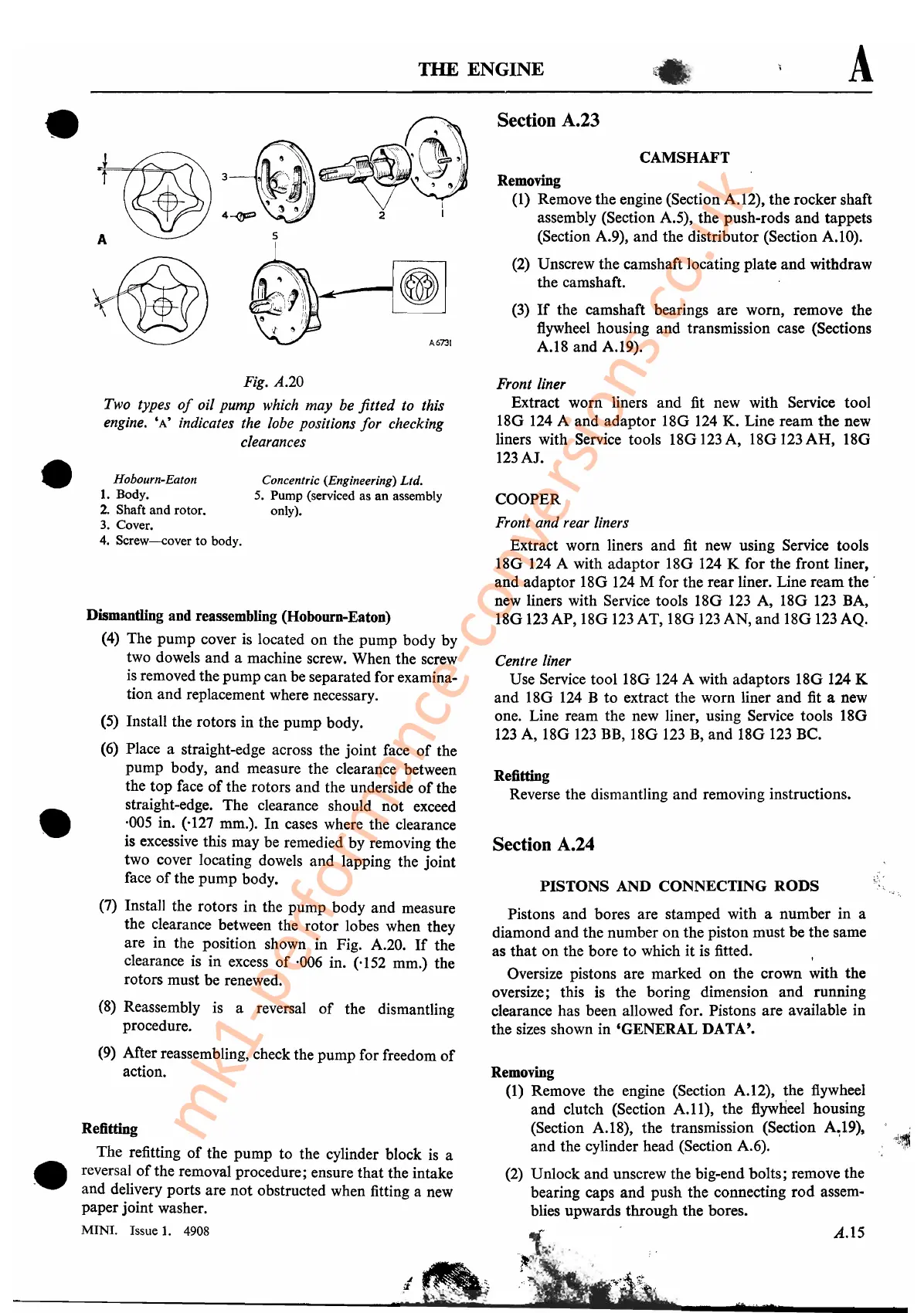
Fig. A.20
Two types
of
oil pump which may be fitted to this
engine.
'A'
indicates the lobe positions
for
checking
clearances
Refitting
The refitting
of
the pump to the cylinder block
is
a
reversal
of
the removal procedure; ensure that the intake
and delivery ports are not obstructed when fitting a new
paper joint washer.
MINI. Issue
1.
4908
A.15
Refitting
Reverse the dismantling and removing instructions.
Front liner
Extract worn liners
and
fit new with Service tool
180
124 A and adaptor
180
124
K. Line ream
the
new
liners with Service tools
180123
A,
180123
AH,
18G
123AJ.
COOPER
Front and rear liners
Extract worn liners
and
fit
new using Service tools
180
124
A with adaptor
180
124 K for the front liner,
and adaptor 18G
124
M for the rear liner. Line ream
the·
new liners with Service tools
180
123
A, 18G
123
BA,
18G
123
AP,
180
123
AT,
180123
AN, and 18G
123
AQ.
Centre liner
Use Service tool
180
124
A with adaptors
180
124 K
and
18G
124
B to extract the worn liner
and
fit a new
one. Line ream the new liner, using Service tools
180
123
A, 18G
123
BB,
180
123
B,
and
180
123
BC.
Pistons and bores are stamped with a number in a
diamond and the number on the piston must be the same
as
that
on the bore to which it is fitted.
Oversize pistons are marked on the crown with the
oversize; this is the boring dimension and running
clearance has been allowed for. Pistons are available in
the sizes shown in 'GENERAL DATA'.
PISTONS
AND CONNECTING
RODS
Section A.24
Removing
(1)
Remove the engine (Section A.12), the flywheel
and clutch (Section
A.ll),
the flywheel housing
(Section A.18), the transmission (Section
A,,:19),
and
the cylinder head (Section A.6).
(2)
Unlock and unscrew the big-end bolts; remove the
bearing caps and push the connecting
rod
assem-
blies upwards through the bores.
Concentric (Engineering) Ltd.
5.
Pump (serviced as
an
assembly
only).
Hobourn-Eaton
1.
Body.
2.
Shaft and rotor.
3.
Cover.
4.
Screw-cover
to body.
Dismantling and reassembling (Hobourn-Eaton)
(4)
The pump cover
is
located on the pump body by
two dowels and a machine screw. When the screw
is
removed the pump can be separated for examina-
tion and replacement where necessary.
(5)
Install the rotors in the pump body.
(6)
Place a straight-edge across the joint face
of
the
pump body, and measure the clearance between
the
top
face
of
the rotors and the underside
of
the
straight-edge. The clearance should not exceed
·005 in. (,127 mm.).
In
cases where the clearance
is excessive this may be remedied by removing the
two cover locating dowels and lapping the joint
face
of
the pump body.
(7) Install the rotors
in
the pump body and measure
the clearance between the rotor lobes when they
are in the position shown in Fig. A.20.
If
the
clearance is in excess
of
·006 in. ('152 mm.) the
rotors must be renewed.
(8)
Reassembly is a reversal
of
the dismantling
procedure.
(9)
After reassembling, check the pump for freedom
of
action.
•
•
•
mk1-performance-conversions.co.uk