THE
CLUTCH
•
•
•
•
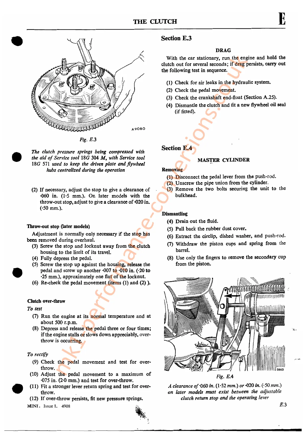
Fig.
E.3
The clutch pressure springs being compressed with
the aid
of
Service tool
18G
304
M,
with Service tool
18G
571
used to keep the driven plate and flywheel
hubs centralized during the operation
(2)
If
necessary, adjust the stop
to
give a clearance
of
·060 in. (1·5 mm.). On later models with the
throw-out stop, adjust to give a clearance
of
·020 in.
(·50 mm.).
Throw-out stop Oater
models)
Adjustment is normally only necessary
if
the stop has
been removed during overhaul.
(3) Screw the stop and locknut away from the clutch
housing to the limit
of
its travel.
(4)
Fully depress the pedal.
(5) Screw the stop up against the housing, release the
pedal and screw up another ·007 to ·010 in. (·20
to
·25 mm.), approximately one flat
of
the locknut.
(6) Re-check the pedal movement (items
(I)
and
(2) ).
Clutch over-throw
To
test
(7)
Run
the engine
at
its normal temperature
and
at
about 500 r.p.m.
(8)
Depress
and
release the pedal three
or
four times;
if
the engine stalls
or
slows down appreciably, over-
throw is occurring.
To
rectify
(9)
Check the pedal movement and test for over-
throw.
(l0) Adjust the pedal movement
to
a maximum
of
·075 in. (2·0 mm.) and test for over-throw.
(11) Fit a stronger lever return spring
and
test for over-
throw.
(12)
If
over-throw persists, fit new pressure springs.
MINI.
Issue
1.
4908
E
Section E.3
DRAG
With the car stationary, run the engine
and
hold the
clutch
out
for several seconds;
if
drag persists, carry
out
the following test in sequence.
(I)
Check for air leaks in the hydraulic system.
(2) Check the pedal movement.
(3) Check the crankshaft end-float (Section A.25).
(4) Dismantle the clutch
and
fit a new flywheel oil seal
(if
fitted).
Section E.4
MASTER CYLINDER
Removing
(l)Disconnect
the pedal lever from the push-rod..
(2) Unscrew the pipe union from the cylinder.
(3)
Remove the two bolts securing the unit
to
the
bulkhead.
Dismantling
(4) Drain
out
the fluid.
(5)
Pull back the rubber dust cover.
(6) Extract the circlip, dished washer,
and
push-rod.
(7) Withdraw the piston cups and spring from the
barrel.
(8) Use only the fingers
to
remove the secondary cup
from the piston.
Fig.
EA
A clearance of·060in. (1·52 mm.) or·020 in. (·50 mm.)
on later models must exist between the adjustable
clutch return stop and the operating lever
E.3
mk1-performance-conversions.co.uk