E
t
THE CLUTCH
•
•
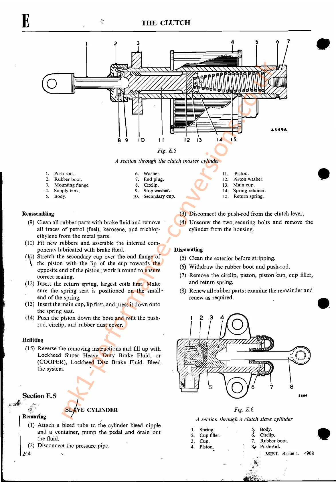
11. Piston.
12. Piston washer.
13.
Main
cup.
14. Spring retainer.
15.
Return
spring.
14
15
12
13
10
6.
Washer.
7.
End
plug.
8. Circlip.
9. Stop washer.
10. Secondary cup.
8 9
I1
Fig. E.5
A section through the clutch master cylinder
1.
Push-rod.
2.
Rubber
boot.
3. Mounting flange.
4. Supply tank.
5.
Body.
Fig. E.6
A section through a clutch slave cylinder
•
•
~.
Body.
6
..
Circlip.
7.
Rubber
boot.
~
Push
..
"Od.
MINtassue
1.
4908
1.
Spring.
2.
Cup
filler.
3. Cup.
4. Piston.
.
(3)
Disconnect the push-rod from the clutch lever.
(4)
Unscrew the two, securing bolts and remove the
cylinder from the housing.
Dismantling
(5)
Clean the exterior before stripping.
(6)
Withdraw the rubber boot and push-rod.
(7)
Remove the circlip, piston, piston
:cup,cup
filler,
and return spring.
(8)
Renew all rubber parts: examine the remainder and
renew as required.
Refitting
(15)
Reverse the removing instructions arid
fill
up with
Lockheed Super Heavy Duty Brake Fluid,
or
(COOPER), Lockheed Disc Brake Fluid. Bleed
the system.
Reassembling
(9)
Clean all rubber parts with brake fluid and remove
all traces
of
petrol (fuel), kerosene, and trichlor-
ethylene from the metal parts. .
(10) Fit new rubbers and assemble the internal com-
ponents lubricated with brake fluid.
(Ill) Stretch the secondary cup over the end flange
of
\ the piston with the lip
of
the cup towards the
opposite end
of
the piston; work it round to ensure
correct sealing;
(12) Insert the return spring, largest coils first. Make
.sure the spring seat
is
positioned on
the
small"
end
of
the spring.
(13) Insert the main cup, lip first, and press it down onto
the spring seat.
~.
(14) Push the piston down the bore and refit the push-
rod, circlip, and rubber dust cover.
Section E.5
"~~·~tach
a
b:t:eC~~~::der
bleed
fipple
and a container, pump the pedal and drain out
the fluid.
(2)
.Disconnect the pressure pipe.
E.4
".
mk1-performance-conversions.co.uk