F
"
THE
TRANSMISSION
(5)
Remove the two end
~pvers.
Note the number
of
•..
shims between the housings and the bearings.
(6)
Unscrew the nuts and remove the differential
assembly.
Dismantling
(7)
Withdraw the two differential bearings with
Service tool 18G
2.
(8)
Remove the differential cage from the driving gear
and extract the gear and thrust washer from the
bore
of
the driving gear.
(9)
Tap
out
the taper pin to release both pinions and
thrust washers, pinion spacer, and the remaining
differential gear and washer.
~
,
o·S~,
'k~'~
,
;;r~~
Fig. F.3
A section through the third motion shaft bearing and
bearing retainer.
It
is essential that the correct thick-
ness
of
shim is used to take
up
the gap indicated
in
the illustration.
Use
the following table
to
ensure that
the correct shim thickness
is
used
Use
shims
When the gap is
totalling
'005 to ·006 in. (·127 to ·152 mm.)
·005 in. (·127 mm.)
·006 to
·008
in. (·152 to
·203
mm.)
·007 in.
(·178
mm.)
'008 to ·010 in.
(·203
to ·254 mm.) ·009 in. (·229 mm.)
'010 to ·012 in. (,254 to ·304 mm.)
·011
in. ('279 mm.)
'012 to ·014 in. ('304 to ·356 mm.)
·013
in. (·330 mm.)
'014 to ·015 in. (·356 to
·381
mm.)
·015
in.
(·381
mm.)
(8) Refit the assembly to the transmission as in Section
~,
F.I,
item (24).
When baulk-ring synchromesh is fitted, the
dismantling and reassembling sequences are the
same, but second, third, and top gear synchroni-
zers are fitted with baulk rings.
If
the first and
second speed gear assembly has been dismantled,
ensure that the plunger in the hub aligns with the
cut-away tooth in the gear
on
assembly.
It
will be
impossible to select first gear otherwise.
Section F.3
DIFFERENTIAL ASSEMBLY
Removing
(1)
Remove the transmission (Section A.19).
(2) Remove the gear-change extension bottom cover
plate.
(3) Remove the clamp screw and withdraw the
remote-control shaft. Take out the nylon seating
and the tension spring from the remote-control
shaft and the shaft lever.
(4) Withdraw the driving flanges from the differential
shafts. Hold the flanges with Service tool
180
669
F.4 while unscrewing
the
nuts.
,.%",.
Reassembling
(10)
Reverse the dismantling procedure.
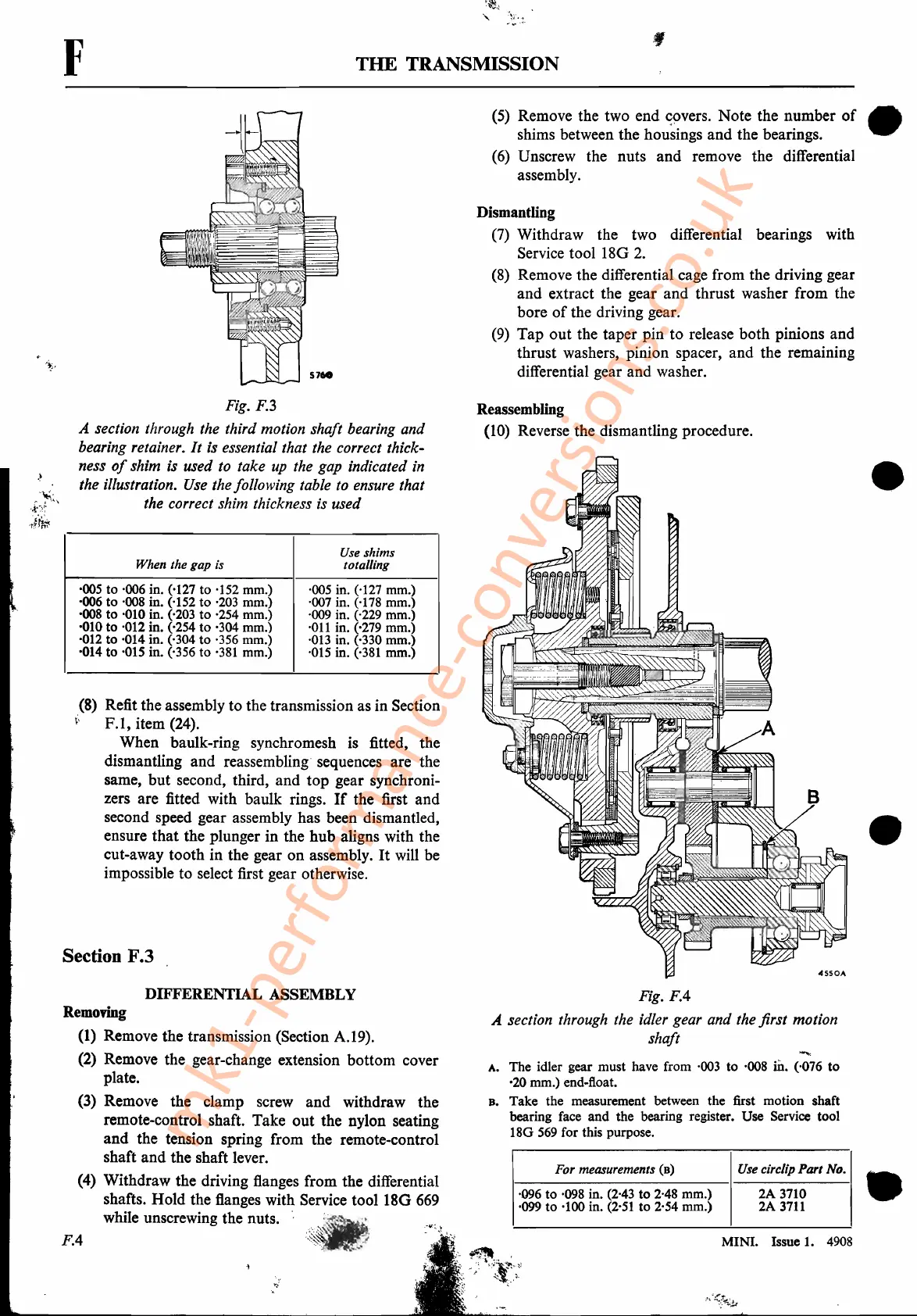
Fig.
FA
A section through the idler gear and the first motion
shaft
A. The idler gear must have from
·003
to ·008
rn.
(·076 to
'20 mm.) end-float.
B. Take the measurement between the first motion shaft
bearing face and the bearing register. Use Service tool
180
569
for this purpose.
For measurements (0) Use circ/ip Part No.
·096 to ·098 in.
(2·43
to 2·48 mm.) 2A 3710
·099 to ·100 in.
(2·51
to 2·54 mm.) 2A
3711
MINI. Issue
1.
4908
.t~~;:
-;-'
•
•
•
mk1-performance-conversions.co.uk