Machine bores
of
cylinder block to this Interference fit
of
Machine liner bore
Engine
Liner
dimension before
Outside diameter
liner in cylinder
to this dimension
type
Part No.
fitting liner
of
liner
block bore after fitting
'A'
(848 c.c.)
2A 784
2·6035
to 2'604 in. 2·606
to
2'60675 in.
·002 to ·00325 in.
2·477
to
2·4785 in.
(66'128 to 66'14 mm.)
(66'19
to
66·21 mm.) ('05 to ·08 mm.)
(62'915
to
62'954 mm.)
997
C.c.
(9F) 12A
391
2·6035 to 2·604 in.
2'606 to 2'60675 in.
·002 to ·00325 in.
2·4570
to
2'4585 in.
(66'128 to 66'14 mm.)
(66'19
to
66·21 mm.) ('05
to
·08 mm.)
(62'408 to 62'445 mm.)
998
C.c.
(9FA)
12G 164
2·64075 to 2·64125 in. 2·64325
to
2·644 in.
·002
to
'00325 in. 2·542
to
2'5435 in.
(67,076 to 67·099 mm.)
(67'139
to
67·158 mm.)
(,05
to
·08 mm.)
(64'571
to
64'608 mm.)
•
THE
ENGINE
A
•
•
•
Section A.25
CRANKSHAFT AND MAIN BEARINGS
Removing
(1)
Carry out the operations described in Section A.24,
items
(1)
and
(2),
and remove the timing cover
(Section A.I6).
(2)
Check the crankshaft end-float.
(3)
Prise out the circlip and slide the pri1nary gear from
the shaft.
(4)
Note that the main bearing caps and crankcase
are numbered; withdraw the caps and bearing
shells.
Do
not interchange caps and shells. The
bottom halves
of
the two thrust washers
will
be
removed with the centre bearing cap. .
(5)
Lift out the crankshaft with the remaining halves
of
the thrust washer and the top half-shells
of
the
main bearings.
(6) Inspect the
crankpi~.,
and journals, and the
bearing shells; regrind', the shaft and
ren~w'
the
bearings as necessary. Permissible regrind dimen-
sions and undersize
bearlii-g
sizes are given in
'GENERAL DATA'. Ensure that all oilway
countersinks are machined to their original
dimensions.
~H;::!
',:'
~i:l
t'H,j~','J
~::~
~
JJJ
~ ~ ~
J
I!
J
f:{
::
:
'"
,
I I i
l......
.t
•
__
...
1
51')8
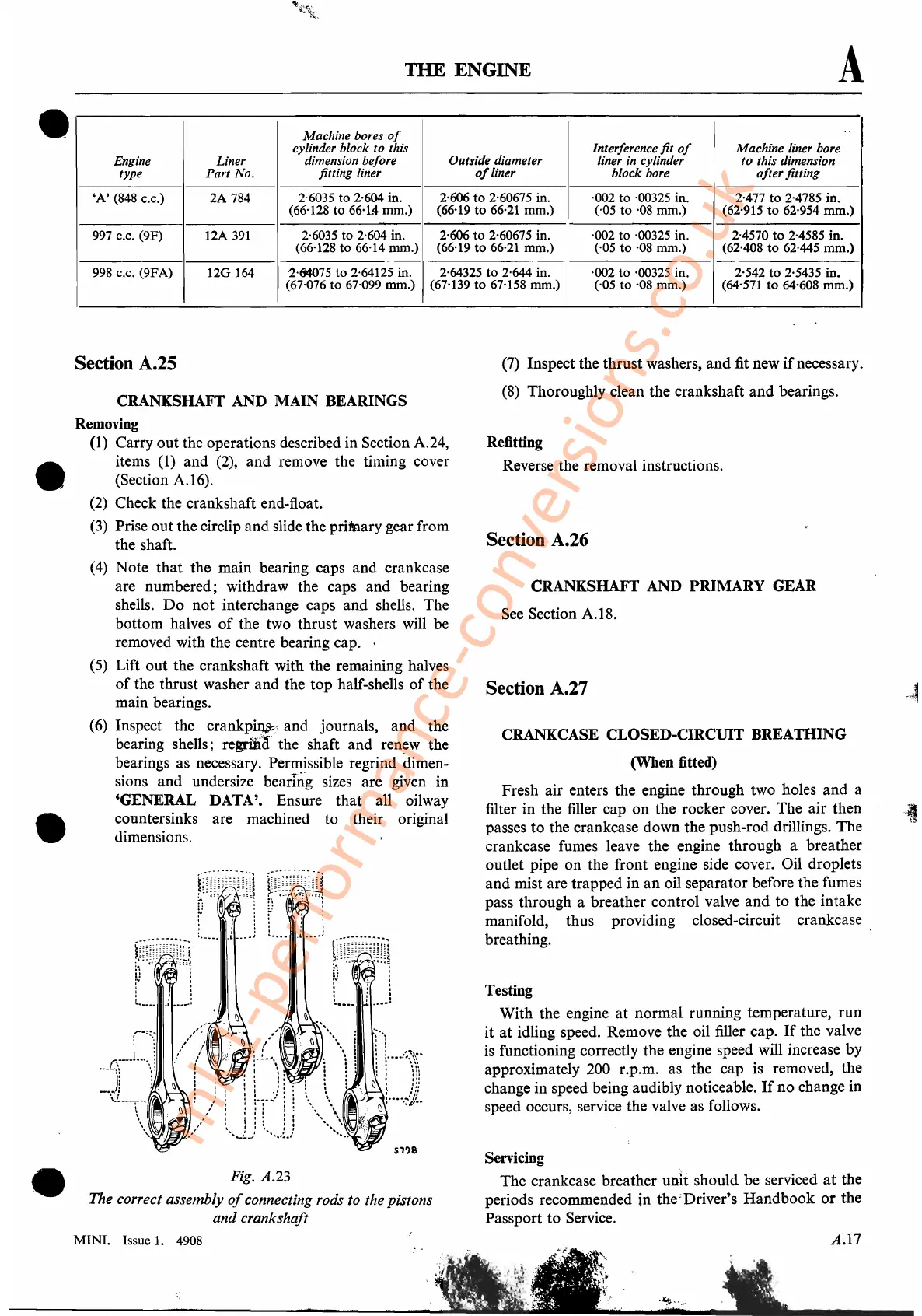
Fig. A.23
The correct assembly
of
connecting rods to the pistons
and crankshaft
MINI.
Issue
1.
4908
(7)
Inspect the thrust washers, and fit new
if
necessary.
(8)
Thoroughly clean the crankshaft and bearings.
Refitting
Reverse the removal instructions.
Section A.26
CRANKSHAFT AND PRIMARY GEAR
See
Section A.I8.
Section A.27
CRANKCASE CLOSED-CIRCUIT BREATHING
(When fitted)
Fresh air enters the engine through two holes and a
filter in the filler cap on the rocker cover. The air then
passes to the crankcase down the push-rod drillings. The
crankcase fumes leave the engine through a breather_
outlet pipe on the front engine side cover. Oil droplets
and mist are trapped in an oil separator before the fumes
pass through a breather control valve and to the intake
manifold, thus providing closed-circuit crankcase
breathing.
Testing
With the engine
at
normal running temperature, run
it
at
idling speed. Remove the oil filler cap.
If
the valve
is
functioning correctly the engine speed will increase by
approximately 200 r.p.m. as the cap is removed, the
change in speed being audibly noticeable.
If
no change in
speed occurs, service the valve as follows.
Servicing
The crankcase breather unit should be serviced
at
the
periods recommended in the:Driver's Handbook or the
Passport to Service.
A.I7
.~"'-.~
.
mk1-performance-conversions.co.uk