M
THE
BRAKING
SYSTEM
Fig.
M.5
The hydraulic pressure regulating valve components
(3)
t.:nscrew
th~
bottom pipe union
and
withdraw
the.
pIpe
and
umon. .
(4)
Remove the intensifier.
Dismantling
(5)
Hold
the intensifier in a
VIce
and
unscrew the
large hexagon plug.
NOTE.-The
plug is under spring pressure.
(6) Extract the piston assembly
and
springs.
(7) Thoroughly clean all parts with brake fluid. and
examine for wear.
Reassembling
(9)
Fit
new parts as required
and
then reverse the
dismantling procedure.
Refitting
Reverse the removal instructions and bleed the system.
Section M.5
Reassembling
(8) Renew all worn
or
damaged parts.
If
the rubber
seals have deteriorated, renew the piston assembly.
Refitting
Reverse the removing instructions.
Bleed the system.
•
PRESSURE REGULATING VALVE
Removing
(1)
Disconnect the three pressure lines, unscrew the
securing
nut
and
withdraw the assembly from the
rear sub-frame cross-member.
Overhauling
(2)
Clean the exterior.
(3)
Remove the end plug
and
sealing washer.
(4)
Extract the valve assembly
and
return spring.
(5)
If
the rubber seals are
not
in good condition, fit a
new piston
and
seal assembly.
(6) Clean all ·parts with brake fluid, reassemble
and
refit.
Section M.6
INTENSIFIER
COOPER (Early models)
The brake intensifier is only fitted
on
early models.
Later models have a pressure regulating valve incorpor-
ated in the system (see Section M.5).
Removing
(1) Slacken the top pipe union, remove the nuts
and
washers and take
out
the mounting bolts.
(2) Completely unscrew the tip union
and
withdraw
the pipe and union.
MA
Section M.7
DISC BRAKE CALLIPER
COOPER
Removing and dismantling
Do
not separate the two halves
of
the calliper; each
piston assembly must be dealt with individually.
(1)
Disconnect the tie-rod from the steering-arm.
(2)
Remove the locking plate from the dust cover.
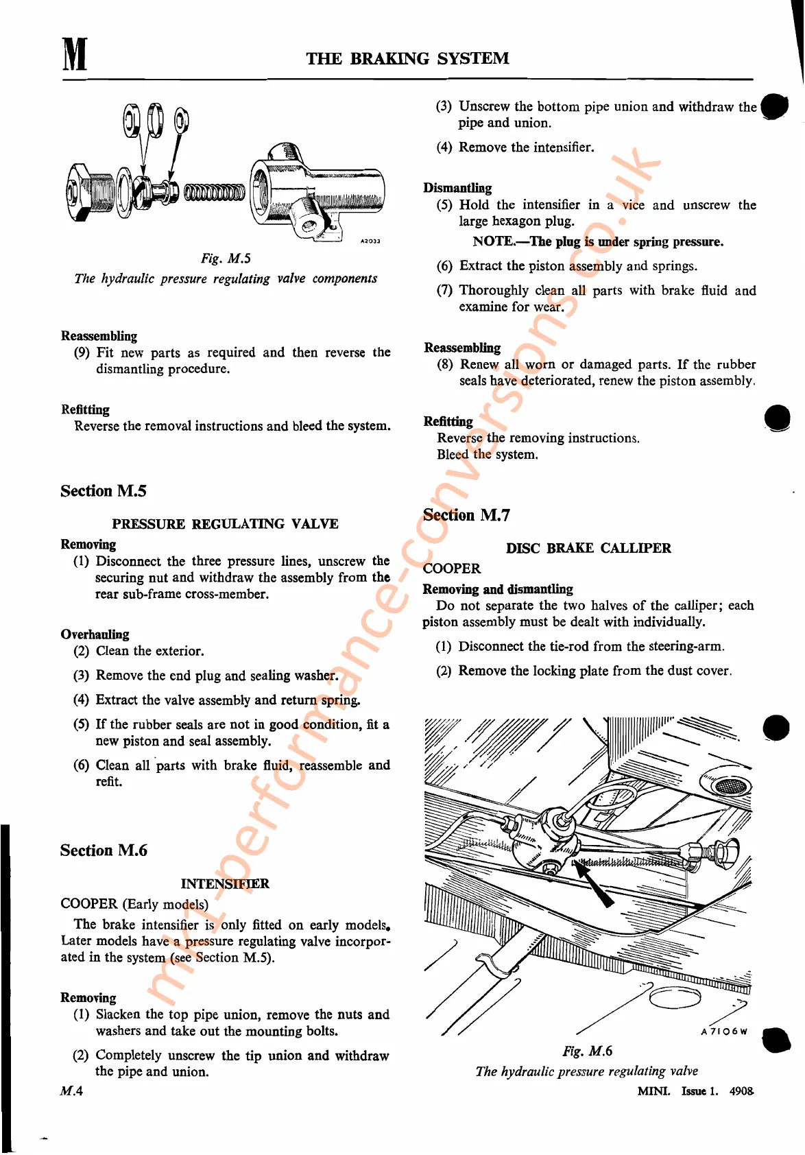
Fig. M.6
The hydraulic pressure regulating valve
MINI. Issue
1.
490&
•
mk1-performance-conversions.co.uk