Refitting
Reverse the above removing instructions. Tighten the
nut
to
the recommended torque (see 'GENERAL
DATA').
Removal
(1)
Disconnect the battery.
(2) Early models. Withdraw the grub screw in the wheel
hub
and
lift
up
the horn switch.
(3)
Mk.
11
models. Carefully prise off the wheel hub
centre cover.
(4) Unscrew the wheel retaining nut and pull off the
wheel.
J
Section
J.l
STEERING-WHEEL
THE
STEERING
•
Section
J.2
STEERING-COLUMN
Removing
(1)
Disconnect the column switch wiring connectors
located below the parcel shelf.
(2) Remove the bolt from the lower column clamp/
steering rack pinion shaft.
(3)
Remove the column upper support clamp bolt.
(4)
Mark
the fitted position
of
the outer column with
the upper support bracket.
(5)
Pull the column assembly upwards and out
of
the
car.
Dismantling
(6)
Remove the steering-wheel as described in Section
J.1.
(7)
Remove
both
halves
of
the column cowl.
(8)
Remove the direction indicator switch and screw
out
the cancelling stud from the column.
(9) Early models. Remove the horn connection slip-
ring assembly.
,.,."
~
, • \ \ \ \ \ L \ \ \
~
\ \
\""
\ \ \ \ \ , \ , , \
~
, \ \ ' I , I
"
.m
••
_
~f'
\\ \
1\\\
\'-
I I
1\\\
:'
I
~
\.'-
; ! : i ;
\!:
(,:'
~\\
: : 1 : /
;)
:!
I:
\
\v
\
: : J : / " I "
;}!--\-----------------
\
t11lf)
.
.:../--1.."';:""
/
-c
U··
~
n
._\\:::::<
Fig.
J.l
Using a locator pin to centralize the rack, with (inset)
the plastic plug
J.2
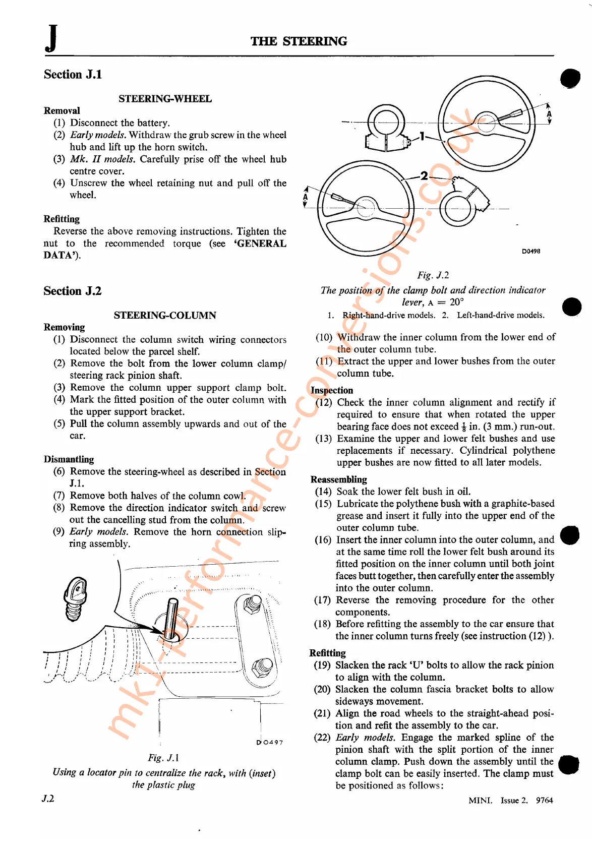
Fig. J.2
The position
of
the clamp bolt
and
direction indicator
lever,
A =
20°
•
1.
Right-hand-drive models.
2.
Left-hand-drive models. .
(10) Withdraw the inner column from the lower end
of
the outer column tube.
(11) Extract the upper and lower bushes from the outer
column tube.
Inspection
(12) Check the inner column alignment
and
rectify
if
required to ensure
that
when rotated the upper
bearing face does
not
exceed
tin.
(3
mm.) run-out.
(13)
Examine the upper
and
lower felt bushes
and
use
replacements
if
necessary. Cylindrical polythene
upper bushes are now fitted to all later models.
Reassembling
(14) Soak the lower felt bush in oil.
(15) Lubricate the polythene bush with a graphite-based
grease
and
insert
it
fully into the upper end
of
the
outer column tube. •
(16) Insert the inner column into the outer column,
and
at
the same time roll the lower felt bush
around
its
fitted position
on
the inner column until
both
joint
faces
butt
together, thencarefully enterthe assembly
into the outer column.
(17) Reverse the removing procedure for the other
components.
(18) Before refitting the assembly
to
the car ensure
that
the inner column turns freely (see instruction (12)).
Refitting
(19) Slacken the rack
'U'
bolts to allow the rack pinion
to
align with the column.
(20) Slacken the column fascia bracket bolts
to
allow
sideways movement.
(21) Align the
road
wheels
to
the straight-ahead posi-
tion
and
refit the assembly
to
the car.
(22) Early models. Engage the marked spline
of
the
pinion shaft with the split portion
of
the inner
column clamp. Push down the assembly until the •
clamp bolt can be easily inserted. The clamp must .
be positioned as follows:
MINI. Issue
2.
9764
mk1-performance-conversions.co.uk