THE
AUTOMATIC TRANSMISSION
Fa
Fig. Fa.31
Centralizing the pump and governor unit
(1) with the
end cover
(2)
using Service
tool18G
1106
(arrowed)
Refitting
(14)
Carry out the instructions given in Section Fa.3,
items
(36)
and
(38).
NOTE.
-
See
'GENERAL
DATA'
for all
torque figures.
Section Fa.6
2
1--r-.--
A6B25A
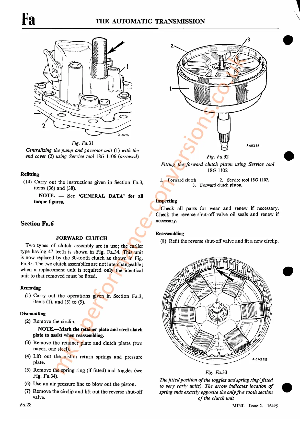
Fig. Fa.32
Fitting the forward clutch piston using Service tool
18G 1102
1.
Forward clutch
2.
Service tool
180
1102.
3. Forward clutch piston.
Inspecting
Check all parts for wear and renew
if
necessary.
Check the reverse shut-off valve oil seals and renew if
necessary.
J
\
•
•
FORWARD
CLUTCH
Two types
of
clutch assembly are in use; the earlier
type having
47
teeth
is
shown in Fig. Fa.34. This unit
is
now replaced by the 30-tooth clutch as shown in Fig.
Fa.35. The two clutch assemblies are notinterchangeable;
when a replacement unit is required only the identical
unit to that removed must be fitted.
Removing
(1)
Carry out the operations given in Section Fa.3,
items
(1),
and
(5)
to
(9).
Dismantling
(2)
Remove the circlip.
NOTE.-Mark
the retainer plate and steel clutch
plate
to
assist when reassembling.
(3)
Remove the retainer plate and clutch plates (two
paper, one steel).
(4)
Lift out the piston return springs and pressure
plate.
(5)
Remove the spring ring (if fitted) and toggles (see
Fig. Fa.34).
(6)
Use an air pressure line to
blowout
the piston.
(7) Remove the circlip and lift out the reverse shut-off
valve.
Fa.28
Reassembling
(8)
Refit the reverse shut-offvalve and
fit
a new circlip.
•
Fig. Fa.33
The fittedposition
of
the toggles andspring ring(fitted
to very early units). The arrow indicates location
of
•
spring ends exactly opposite the onlyfive tooth section
of
the clutch unit
MINI. Issue 2.
16495
mk1-performance-conversions.co.uk