(5)
Remove the shaft locating screw from the front
•.
bracket.
(6) Withdraw the split pin and washers from the front
end
of
the"'rnaft.
(7)
Slide the rockers, brackets
and
springs from the
shaft, noting their relative positions for correct
refitting.
(8)
Unscrew the plug from the front end
of
the shaft
and clean
out
the oilways.
,."
To
fit
new bushes
(9) Remove the old ,and press in new bushes with •
Service tool 18G 226 and 18G 226 A.
"',.,
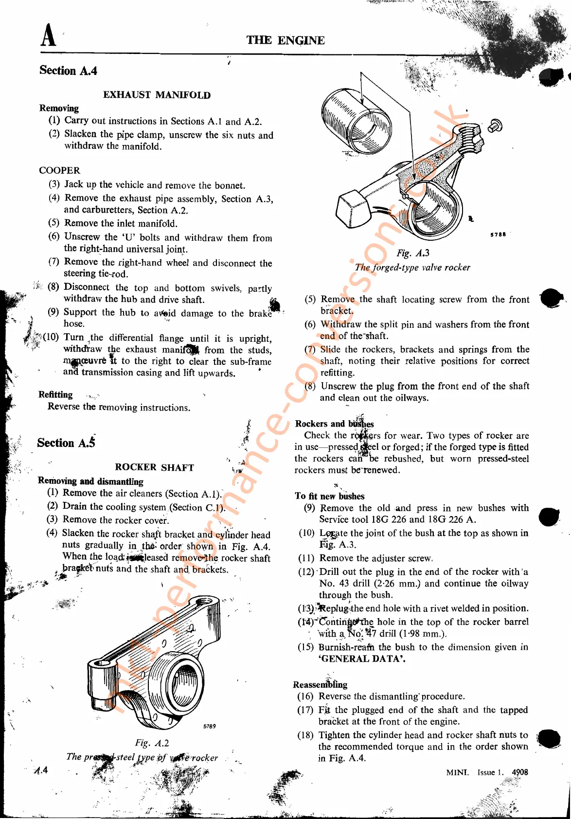
(l0)
I:.~tethejoint
of
the bush
at
the
top
as shown in
Eig. A.3.
(11) Remove the adjuster screw.
(12)' Drill
out
the plug in the end
of
the rocker with 'a
No. 43 drill (2,26 mm.) and continue the oilway
through
the bush.
(t3J.~~eplui:the
end hole with a rivet welded in position.
(1'4)"""C"?liti~b~
hole in the top
of
the rocker barrel
';
'with~.
No:
~7
drill (1,98 mm.).
(15)
Burriish-r;m
the bush to the dimension given in
'GENERAL DATA'.
Fig.
A.3
The forged-type valve rocker
,''''(''. .
Rockers
and
b~~
Check the
r~~rs
for wear. Two types
of
rocker are
in
use-presse~~e1
or
forged;
if
the forged type is fitted
the rockers can
'he
rebushed,
but
worn pressed-steel
rockers must be"renewed.
Reassemtfing
(16) Reverse the dismantling'procedure.
(17)
Fit
the plugged end
of
the shaft
and
the tapped
bracket
at
the front
of
the engine.
(18) Tighten the cylinder head
and
rocker shaft nuts
to
.','"
the recommended torque and in the order shown
in Fig.
AA.
THE ENGINE
EXHAUST
MANIFOLD
Fig. A.2
The
pr,~steetgpeiJf
~e:~;~'W
'.
'3;,'>~~t~>'-
.
",
,;3~'{~
.-;.
~{
",
A
Section A.4
Section
A.~
i(.4
",
tA,
ROCKER SHAFT
~flr'
Removing
and
dismantling
(1)
Remove the air cleaners (Section
A.1)."
(2) Drain the cooling system,(Section
C.l).
(3) Remove the rocker
cover'.
'
.'
(4)
Slacken the rocker shaft
bracketand
cyi~rider
head
nuts gradually i!1.,th6: order' shown in Fig.
AA.
When
the
10~Q;~leased'
remov~lhe
rocker shaft
• ,l>raf.¥et;'outs
and
the shaft and, brackets.
",~,
,::r~'
•
~.;-;:.~~."
Removing
(1)
Carry
out
instructions
in
Sections
A.l
and
A.2.
(2) Slacken the pipe clamp, unscrew the six nuts and
withdraw the manifold.
Refitting
Reverse the removing instructions.
COOPER
(3) Jack up the vehicle
and
remove the bonnet.
(4)
Remove the exhaust pipe assembly, Section A.3,
and
carburetters, Section A.2.
(5) Remove the inlet manifold.
(6) Unscrew the
'U'
bolts and withdraw them from
the
right~hand
universal join.t.
(7) Remove the right-hand wheel and disconnect the
steering tie-rod.
(8) Disconnect the
top
and bottom swivels,
pa.w:tly
withdraw the
hub
and
drive shaft. •
\ (9) Support the
hub
to
a~!d
damage
to
the
brake'
~
.,
y hose. "
t~(lO)
T~m
,the differential
flang~
until it
is
upright,
y'
Wlthdtaw
~4e
exhaust manifcllr from the studs,
l11fl..<eUvre
ft
to the right
to
clear the sub-frame
.
ana
transmission casing and lift upwards. •
mk1-performance-conversions.co.uk