A
DE(;~~,IZING
(1) Remove the
cylindefli~ad
aIld gasket(Soction A.6)
and the valves (Section
A.8),c;;~1:#~
(2) Scrape the carbon
from~the
piston
crow~~
~ylirider
head,valves,
and
cylinder block, leaving a ring
of
carbon around the periphery
of
~<lwach
pistoJ\,and
the top
of
each bore. Blow all deposits
of
carbon
from the head
and
block. r
(3)
Refit the cylinder head (Section A.6).
Section A.7
(5) Remove the rocker cover, rocker shaft, push-rods,
sparking plugs,
and
the three screws securing
the
radiator tie-plate to the thermostat housing.
(6) Disconnect the radiator
to
cylinder head hose,
the suction advance pipe from the clip
on
the water
inlet pipe
and
the heater hose from the water
valve
at
the rear
of
the cylinder head.
(7)
Slacken the water by-pass hose.
(8) Remove the remaining cylinder head nuts.
NOTE.-The
Cooper
'8'
has an additional bolt
at
the front
of
the cylinder head.
(9)
Lift the head squarely.
If
the
joint
sticks,
tap
each
side
of
the head with a wooden
or
hide mallet.
Lift the gasket from the studs.
Refitting
Reverse the removing procedure"
noting the following
points.
"'.
(10) Tforoughly clean the faces
of
the cylinder, head
•
and
the top
of
the block,
and
,):1t
a new
g~sket
without jointing compound
or,
grease,~~e
g~!et
is
marked
'TOP'
and
'FRONT
. cje,;,;/7:,
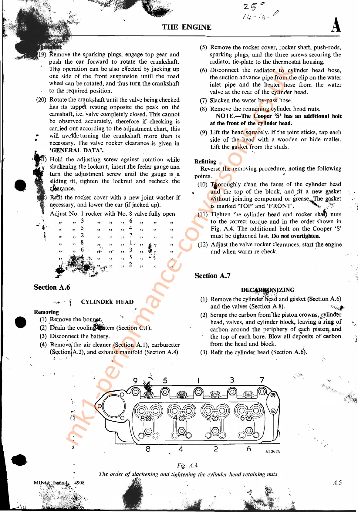
(11) Tighten the cylinder head and rocker
sh~
nuts
to the correct torque and in the order shown in
Fig.
AA.
The additional bolt
on
the
Cooper'S'
must be tightened last. Do not overtighten.
(12) Adjust the valve rocker clearances, start the engine
and when warm re-check. .
"
THE
ENGINE
"
"
19)
~~ove
the sparking plugs, engage top gear and
push the car forward to rotate the crankshaft.
Tili,s
operation can be also effected by jacking up
one side
of
the front suspension until the road
wheel can be rotated, and thus
turn
the crankshaft
to the required position.
(20) Rotate the
cr~nk_shaft
until the valve being checked
has its
tappJt
resting. opposite the peak
on
the
camshaft, i.e, valve completely closed. This cannot
be observed accurately, therefore
if
checking
is
carried
out
according to the adjustment chart, this
will
avot<1.:
turning the crankshaft more
than
is
necessary. The valve rocker clearance ,is given in
'GENERAL DATA'•
.
c)
Hold the adjusting screw against rotation while
c I slackening the locknut, insert .the feeler gauge and
,turn the adjustment. screw until the gauge is a
sliding fit, tighten the locknut and recheck the
.c!ealfl
nce
.
)
i~~t
the rocker cover with a new joint washer
if
n~cessary,
and lower the car (ifjacked up).
\,
Adjust No. I rocker with No. 8 valve fully open
~
"
,,3
""
6""
"
-:
'H"
5
""
4""
"
, "
,,2
"""7,,
" "
"
,,8
"""
1
c'c'
" i
'?
"
"
,,6,
,;.1"""
3
"i"
"
5
;";:l
"
""
2 "
,.
•
•
Section A.6
~
...
~
- f CYLINDER HEAD
Remo~g
.
'.
(0
Remove the bony.p:.
...
(2) "rlrain the
coolin"tem
(Section
C.l).
(3)
Disco~nect
the battery.
(4) Remova;the air cleaner (Section A.I), carburetter
(S((CtioniA.2),
and
exhaust manifold (Section AA).
'.",
'f:;:
...
\
'f""!,
I:
...
!i~
Fig.
AA
The order
of
s!qpkening and tightening the cylinder head retaining nuts
1,."
~.:i.~
-
A.5
mk1-performance-conversions.co.uk