A
THE
ENGINE
•
,
...
- ....
~-
•
49Qf'
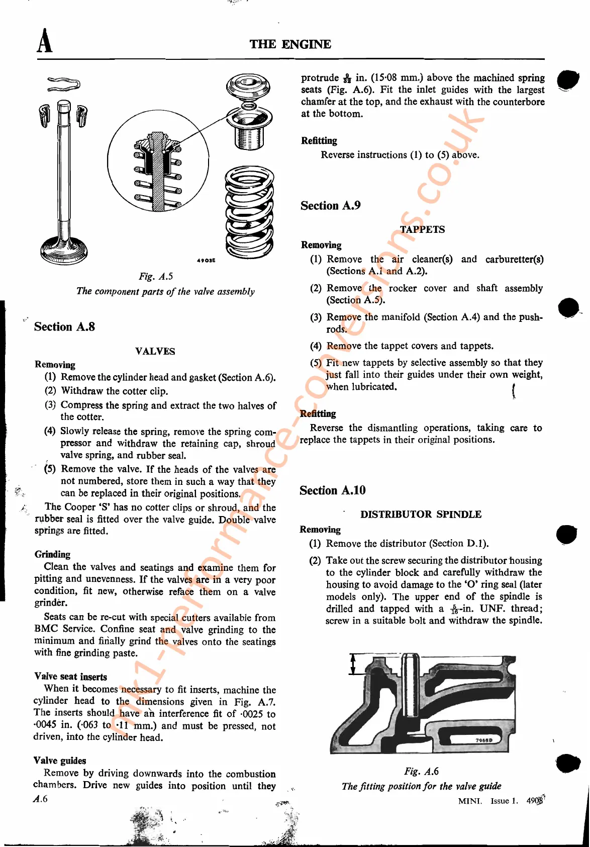
Fig. A.6
The fitting position
for
the valve guide
MINI.
Issue
1.
Removing
(1)
Remove the distributor (Section
0.1).
(2)
Take outthe screw securing the distributorhousing
to the cylinder block and carefully withdraw the
housing to avoid damage to the
'0'
ring seal (later
models only). The upper end
of
the spindle
is
drilled and tapped with a
-&--in.
UNF.
thread;
screw in a suitable bolt and withdraw the spindle.
DISTRIBUTOR SPINDLE
TAPPETS
Refitting
Reverse instructions (1) to (5) above.
Removing
(1) Remove the air cleaner(s) and carburetter(s)
(Sections
A.l
and A.2).
(2)
Remove the rocker cover and shaft assembly
(Section A.5).
(3)
Remove the manifold (Section
AA)
and the push-
rods.
(4)
Remove the tappet covers and tappets.
(5)
Fit new tappets by selective assembly so that they
just fall into their guides under their own weight,
when lubricated.
{,
Refitting
Reverse the dismantling operations, taking care to
replace the tappets in their original positions.
protrude
If
in. (15'08 mm.) above the machined spring •
seats (Fig. A.6). Fit the inlet guides with the largest ',-,'
chamfer
at
the top, and the exhaust with the counterbore
at
the bottom.
Section A.9
Section
A.tO
4901£
Fig. A.5
The component parts
of
the valve assembly
Removing
(1)
Remove the cylinder head and gasket (Section A.6).
(2)
Withdraw the cotter clip.
(3)
Compress the spring and extract the two halves
of
the cotter.
e
4)
Slowly release the spring, remove the spring com-
pressor
and
withdraw the retaining cap, shroud
, valve spring, and rubber seal.
(5)
Remove the valve.
If
the heads
of
the valves are
not numbered, store them in such a way that they
can be replaced in their original positions.
The
Cooper'S'
has no cotter clips
or
shroud, and the
I1lbber seal
is
fitted over the valve guide. Double valve
springs are fitted.
Grinding
Clean the valves and seatings and examine them for
pitting and unevenness.
If
the valves are in a very poor
condition, fit new, otherwise reface them
on
a valve
grinder.
Seats can be re-cut with special cutters available from
BMC Service. Confine seat and valve grinding to the
minimum and finally grind the valves onto the seatings
with fine grinding paste.
VALVES
Valve
seat
inserts
When
it
becomes necessary to fit inserts, machine the
cylinder head to the dimensions given in Fig. A.
7.
The inserts should have
an
interference fit
of
·0025 to
·0045 in. (,063 to
·11
mm.) and must be pressed, not
driven, into the cylinder head.
Valve guides
Remove by driving downwards into the combustion
chambers. Drive new guides into position until they
A.6
Section A.8
mk1-performance-conversions.co.uk