THE
ENGINE
FLYWHEEL
HOUSING
AND PRIMARY GEAR
Removing •
(I)
Remove the engine (Section A.12). . "
(2)
Remove the flywheel and clutch assembly (Section
A.ll).
(3)
Remove the screws and nuts securing the housing;
note their positions for correct replacement.
•
VAL
VE
TIMING
Checking
(I) Adjust the rocker clearance
of
No. I inlet valve to
·019 in. (,48 mm.), ·021 in. (,53 mm.)
Cooper'S',
and turn the crankshaft until the valve is about to
open.
(2)
Take off the
flywheel
inspection hole cover. The
pointer should now be opposite the
5°
mark on
the flywheel.
(3)
After checking, reset the rocker clearance
of
No. 1
inlet valve to
·011 in. (,28
mm.)-engine
hot.
Section A.17
Section A.18
1
A
Fig.
A.13
The timing gears assembled into the timing
chain
with the two marks
on
the gears opposite each other
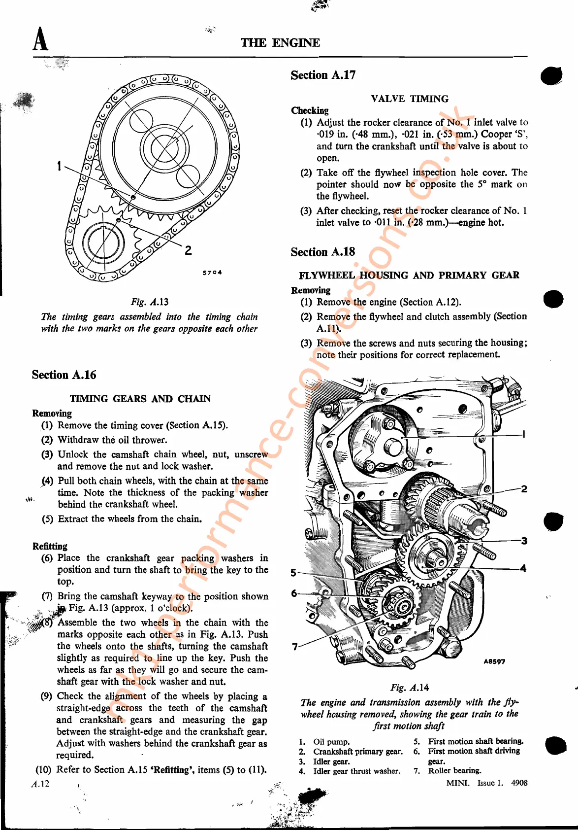
1.
Oil pump.
2.
Crankshaft primary gear.
3.
Idler gear.
4. Idler gear thrust washer.
Section A.16
TIMING GEARS AND CHAIN
Removing
(I)
Remove the timing cover (Section A.IS).
(2) Withdraw the oil thrower.
(3) Unlock the camshaft chain wheel, nut, unscrew
and remove the nut and lock washer.
{4)
Pull both chain wheels, with the chain
at
the same
. time. Note the thickness
of
the packing washer
,\t,
behind the crankshaft wheel.
(5) Extract the wheels from the chain.
Refitting
(6) Place the crankshaft gear packing washers in
position and turn the shaft to bring the key to the
top.
(7) Bring the camshaft keyway to the position shown
,<,.i!i1,,;·Fi
g
. A.I3 (approx. I o'clock).
.
~",v·.t,fjtj--
Assemble
th~
two wheels in
~he
~hain
with the
,;;*:>" ' marks
OppOSIte
each other as
In
FIg. A.l3. Push
vf;;:Y
the wheels onto the shafts, turning the camshaft
slightly as required to line up the key. Push the
wheels as far as they will go and secure the cam-
shaft gear with the lock washer and nut.
(9) Check the alignment
of
the wheels by placing a
straight-edge across the teeth
of
the camshaft
and crankshaft gears and measuring the gap
between the straight-edge and the crankshaft gear.
Adjust with washers behind the crankshaft gear as
required.
(10) Refer to Section A.IS
'Refitting', items (5) to (11).
A.12
I.
Fig.
A.14
The engine and transmission assembly with the
fly-
wheel housing removed, showing the gear train to the
first motion shaft
5.
First motion shaft bearing.
6.
First motion shaft driving
gear.
7.
Roller bearing.
MINI. Issue
1.
4908
•
•
..
mk1-performance-conversions.co.uk