G
THE
DRIVE
SHAFTS
GENERAL
DESCRIPTION
Each
of
the two drive shafts employed has two prin-
ciple members incorporating a Hardy Spicer constant-
velocity bell joint. The hemispherical interior
of
the bell
joint and the exterior
of
the inner ball race have
six
grooves machined in line with the shaft axis, and a ball
cage carrying six steel balls is interposed between the two.
The steel balls engage the grooves
of
both members to
key them together and
at
the same time allow the mem-
bers to hinge freely upon each other.
The joint
is
packed with special grease and the unit
is
enclosed in a sealed rubber boot. The inner end
of
the
drive shaft is splined and has a pre-Iubricated sliding
joined sealed with a rubber boot.
Section
G.l
DRIVE SHAFTS
Removing
To remove the drive shaft assembly from the vehicle
follow the removing instructions given for swivel hubs in
Section K.3.
The constant-velocity bell joint may
be
removed from
the drive shaft for replacement as a unit
or
to have a
Service kit fitted. Under no circumstances must individual
components be replaced in the bell joint assembly.
Should a rubber boot enclosing the joint be damaged
with a consequent loss
of
lubricant,
it
is
necessary to
remove the joint from the shaft for dismantling and
inspection
of
the components.
If
a rubber
boot
is damaged in the workshop and
dirt has not entered the joint, a new boot may be fitted
after first repacking the joint with the recommended
grease.
To fit a new boot the drive shaft must be removed
from the vehicle.
Constant-velocity (bell) joint
The bell joint can be removed from the drive shaft
for dismantling and inspection
of
the components.
Service kits are available which include the required
amount
of
lubricant to service a bell joint.
When servicing
of
the joint becomes necessary, the
procedure given in Section G.2 must be followed.
Sliding joint flange
On later models the sliding
joint
is prepacked with
-l
oz.
(21
gm.)
of
Duckham's M.B. grease (BMC pack
AKF
1457) and sealed with a rubber housing seal, early
models were fitted with lubricating nipple. When servicing
the
sliding
joint
or fitting a new seal, refer to Section G.2.
G.2
Section G.2 •
~
SERVICING
Dismantling the shaft assembly
(1)
Clean the shaft
of
road dirt and grease
and
mount
the shaft centrally in a vice fitted with soft jaws.
(2) Prise off the boot and housing seal clips
or
cut the
soft iron wire,
turn
back the housing seal
and
slide
off the joint flange. Remove the housing seal and
the rubber boot,
if
they are worn
or
damaged
replacements must be fitted
on
reassembly.
(3) The bell
joint
can only be dismantled after removal
of
the shaft; a round-section spring ring located
in a deep groove in the extreme end
of
the shaft
is
expanded into the chamfered end
of
the inner
race bore,
and
for shaft removal this must be
contracted into the groove.
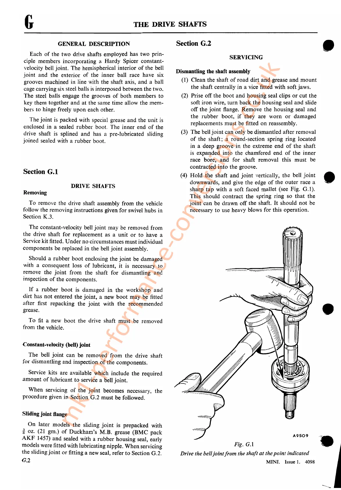
(4) Hold the shaft
and
joint
vertically, the bell joint •
downwards, and give the edge
of
the outer race a
sharp
tap
with a soft faced mallet (see Fig.
G.l).
This should contract the spring ring so that the
joint can be drawn off the shaft.
It
should not be
necessary to use heavy blows for this operation.
•
Fig.
G.l
Drive the bell
joint
from
the shaft
at
thepoint indicated
MINI.
Issue
1.
4098
mk1-performance-conversions.co.uk



 To Next Page