THE
DRIVE
SHAFTS
• Dismantling the joint
(5)
The joint should
be
dismantled only if there
is
reason to believe that it
is
still serviceable.
(6)
As
the components are mated and have operated
together, they must be kept in the same mating
relationship. The relative positions
of
the inner
and outer races and the cage should be marked
with blue marker or a paint which
will
not wash
off when the parts are cleaned.
(7) With the shaft withdrawn the inner race can
swivel
freely, tilt the inner race until one ball
is
released
(Fig. G.2). Note that the cage
swivels
through half
the angle
of
the inner race.
If
the joint
is
sticky
with grease each ball may be eased out
in
turn
with a pointed tool.
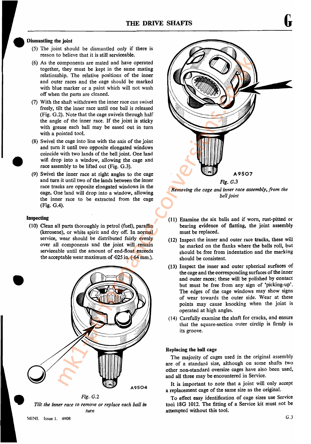
(8)
Swivel
the cage into line with the axis
of
the joint
and turn it until two opposite elongated windows
coincide with two lands
of
the bell joint. One land
•
will
drop into a window, allowing the cage and
race assembly to be lifted out (Fig. G.3).
(9)
Swivel
the inner race
at
right angles to the cage
and turn it until two
of
the lands between the inner
race tracks are opposite elongated windows in the
cage. One land
will
drop into a window, allowing
the inner race to be extracted from the cage
(Fig. G.4).
Inspecting
(10) Clean all parts thoroughly in petrol (fuel), paraffin
(kerosene), or white spirit and dry
off.
In
normal
service, wear should be distributed fairly evenly
over all components and the joint
will
remain
serviceable until the amount
of
end-float exceeds
the acceptable wear maximum
of
·025
in. (,64 mm.).
•
Fig. G.2
Tilt the inner race to remove or rep/ace each ball in
turn
MINI.
Issue
1.
4908
G
A9507
Fig. G.3
Removing the cage
and
inner race assembly,
from
the
belljoint
(11)
Examine the six balls and
if
worn, rust-pitted or
bearing evidence
of
flatting, the joint assembly
must be replaced.
(12)
Inspect the inner and outer race tracks, these
will
be marked on the flanks where the balls roll, but
should be free from indentation and the marking
should be consistent.
(13)
Inspect the inner and outer spherical surfaces of
the cage andthe corresponding surfaces
of
the inner
and outer races; these will be polished by contact
but must be free from any sign
of
'picking-up'.
The edges
of
the cage windows may show signs
of
wear towards the outer side. Wear
at
these
points may cause knocking when the joint
is
operated
at
high angles.
(14)
Carefully examine the shaft for cracks, and ensure
that the square-section outer circlip
is
firmly
in
its groove.
Replacing
the
ball cage
The majority
of
cages used in the original assembly
are
of
a standard size, although on some shafts two
other non-standard oversize cages have also been used,
and all three may be encountered in Service.
It
is important to note that a joint will only accept
a replacement cage
of
the same size as the original.
To effect easy identification
of
cage sizes use Service
tool 18G
1012.
The fitting
of
a Service kit must not
be
attempted without this tool.
G.3
mk1-performance-conversions.co.uk



 To Next Page