THE
DRIVE SHAFTS
G
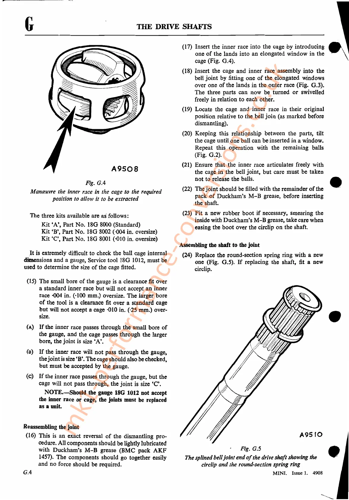
A9508
Fig.
G.4
M
anceuvre
the
inner
race
in
the
cage
to
the
required
position
to
allow
it
to
be
extracted
The three kits available are
as
follows:
Kit
'A',
Part
No.
180
8000 (Standard)
Kit
'B',
Part
No.
180
8002 (,004 in. oversize)
Kit
'C',
Part
No.
180
8POI
(,010 in. oversize)
It
is extremely difficult
to
check the ball cage internal
cIfalensions
and
a gauge, Service tool
180
1012, must be
used
to
determine the size
of
the cage fitted.
(17) Insert the inner race into the cage
by
introducing
one
of
the lands into
an
elongated window in the
cage (Fig.
0.4).
(18) Insert the cage
and
inner race assembly
into
the
bell
joint
by fitting one
of
the elongated windows
over one
of
the lands
in
the outer race (Fig. 0.3).
The three parts
can
now be turned
or
swivelled
freely
in
relation
to
each other.
(19) Locate the cage
and
inner race in their original
position relative
to
the bell
join
(as marked before
dismantling).
(20) Keeping this relationship between the parts, tilt
the cage until one ball can be inserted
in
a window.
Repeat this operation with the remaining balls
(Fig.
0.2).
(21) Ensure
that
the inner race articulates freely with
the cage
in
the bell joint,
but
care must be taken
not
to
release the balls.
(22)
The
joint
should be filled with the remainder
of
the
pack
of
Duckham's
M-B
grease, before inserting
the shaft.
(23)
Fit
a new rubber
boot
if
necessary, smearing the
inside with Duckham's
M-B
grease, take care when
easing the
boot
over the circlip
on
the shaft.
Assembling the shaft to the joint
(24) Replace the round-section spring ring with a new
one (Fig.
0.5).
If
replacing the shaft, fit a new
circlip.
•
(15) The small bore
of
the gauge is a clearance fit over
a standard inner race
but
will
not
accept
an
inner
race ·004 in. (·100 mm.) oversize. The larger bore
of
the tool is a clearance fit over a standard cage
but
will
not
accept a cage ·010 in. (,25 mm.) over-
size.
(A)
If
the inner race passes through the small bore
of
the gauge,
and
the cage passes through the larger
bore, the
joint
is size
'A'.
(B)
If
the inner race will
not
pass through the gauge,
the
joint
is size 'B'. Thecage should also
be
checked,
but
must be accepted by the gauge.
(c)
If
the inner race passes through the gauge,
but
the
cage will
not
pass through, the
joint
is size
'C'.
NOTE.-Should
the gauge 18G 1012 not accept
the inner race
or
cage, the joints must be replaced
as a unit.
Reassembling the joint
(16) This is
an
exact reversal
of
the dismantling pro-
cedure. All components should be lightly lubricated
with Duckham's
M-B
grease
(BMC
pack
AKF
1457). The components should go together easily
and
no
force should be required.
G.4
•
A9SfO
Fig.G.5 •
The
splined belljoint end
of
the
drive
shaft showing the . .
circlip
and the round-section
spring
ring
MINI. Issue
1.
4908
mk1-performance-conversions.co.uk



 To Next Page