THE DRIVE SHAFTS
•
•
•
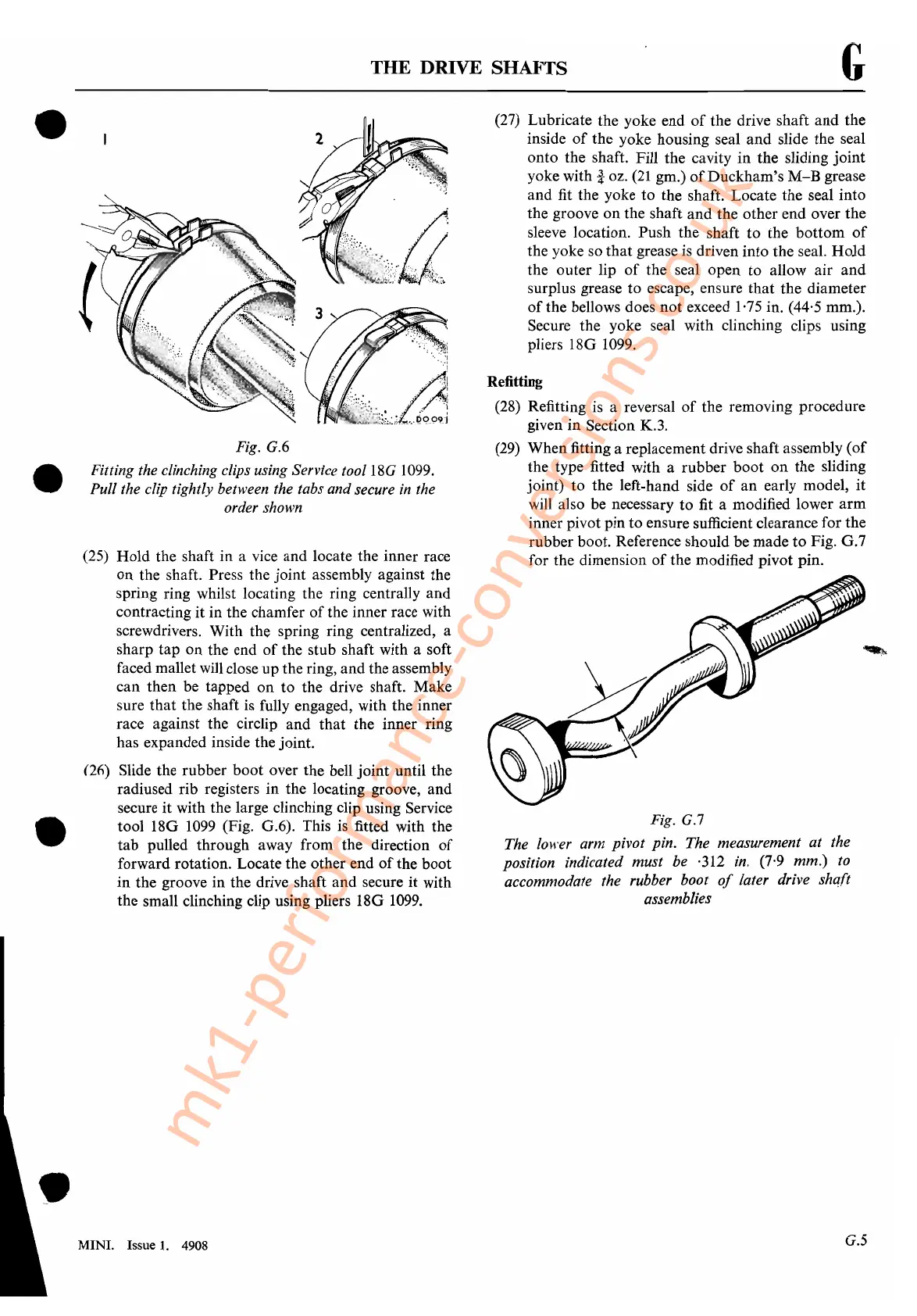
Fig. G.6
Fitting the clinching clips using Service tool18G 1099.
Pull the clip tightly between the tabs and secure
in
the
order shown
(25)
Hold
the shaft in a vice and locate the inner race
on
the shaft. Press the joint assembly against the
spring ring whilst locating the ring centrally and
contracting it in the chamfer
of
the inner race with
screwdrivers. With the spring ring centralized, a
sharp tap on the end
of
the stub shaft with a soft
faced mallet will close
up
the ring, and the assembly
can then be tapped
on
to the drive shaft. Make
sure that the shaft
is
fully engaged, with the inner
race against the circlip and that the inner ring
has expanded inside the joint.
(20) Slide the rubber
boot
over the bell joint until the
radiused rib registers in the locating groove, and
secure
it
with the large clinching clip using Service
tool 18G
1099
(Fig. G.6). This
is
fitted with the
tab
pulled through away from the direction
of
forward rotation. Locate the other end
of
the boot
in
the groove in the drive shaft and secure it with
the small clinching clip using pliers 18G
1099.
MINI.
Issue
1.
4908
G
(27) Lubricate the yoke end
of
the drive shaft
and
the
inside
of
the yoke housing seal
and
slide the seal
onto the shaft. Fill the cavity
in
the sliding joint
yoke with
i oz.
(21
gm.)
of
Duckham's
M-B
grease
and fit the yoke to the shaft. Locate the seal into
the groove on the shaft
and
the other end over the
sleeve location. Push the shaft
to
the
bottom
of
the yoke so that grease is driven into the seal. Hold
the outer lip
of
the seal open to allow air
and
surplus grease to escape, ensure
that
the diameter
of
the bellows does not exceed
1·75
in. (44,5 mm.).
Secure the yoke seal with clinching clips using
pliers 18G
1099.
Refitting
(28) Refitting is a reversal
of
the removing procedure
given in Section K.3.
(29) When fitting a replacement drive shaft assembly
(of
the type fitted with a rubber boot
on
the sliding
joint) to the left-hand side
of
an early model,
it
will also be necessary to fit a modified lower
arm
inner pivot pin
to
ensure sufficient clearance for the
rubber boot. Reference should be made
to
Fig. G.7
for the dimension
of
the modified pivot pin.
Fig. G.7
The lower arm pivot pin. The measurement
at
the
position indicated must be
·312
in.
(7·9 mm.)
to
accommodate the rubber boot
of
later drive shqft
assemblies
G.5
mk1-performance-conversions.co.uk



 To Next Page