THE
COOLING SYSTEM
•
•
•
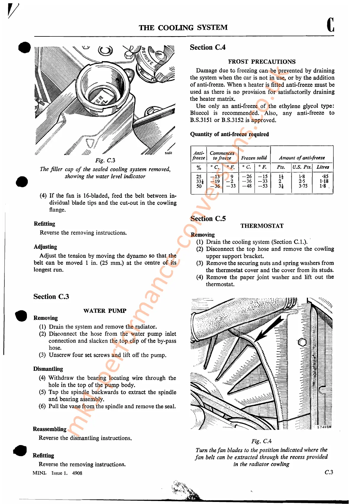
Fig. C.3
The filler cap
of
the sealed cooling system removed,
showing the water level indicator
(4)
If
the fan is 16-bladed, feed the belt between in-
dividual blade tips
and
the cut-out in the cowling
flange.
Refitting
Reverse the removing instructions.
Adjusting
Adjust the tension by moving the dynamo so
that
the
belt
can
be moved 1 in. (25 mm.)
at
the centre
of
its
longest run.
Section C.3
WATER
PUMP
Removing
(1) Drain the system
and
remove the radiator.
(2) Disconnect the hose from the water
pump
inlet
connection
and
slacken the
top
clip
of
the by-pass
hose.
(3) Unscrew four set screws
and
lift off the pump.
Dismantling
(4) Withdraw the bearing locating wire through the
hole
in
the
top
of
the
pump
body.
(5)
Tap
the spindle backwards
to
extract the spindle
and
bearing assembly.
(6) Pull the vane from the spindle
and
remove the seal.
Reassembling
Reverse the dismantling instructions.
Refitting
Reverse the removing instructions.
MINI. Issue
1.
4908
Section C.4
FROST
PRECAUTIONS
Damage due
to
freezing
can
be prevented
by
draining
the system when
the
car
is
not
in
use,
or
by
the
addition
of
anti-freeze.
When
a heater is fitted anti-freeze
must
be
used as there is
no
provision for satisfactorily draining
the heater matrix.
Use only
an
anti-freeze
of
the ethylene glycol type:
Bluecol is recommended. Also, any anti-freeze
to
B.S.3151
or
B.S.3152 is approved.
Quantity
of
anti-freeze required
Anti-
Commences
freeze
to freeze Frozen solid Amount
of
anti-freeze
%
o
C.
OF.
o
C.
of.
Pts.
U.S. Pts. Litres
--
--
--
--
25
-13
9
-26
-15
l!-
1·8 ·85
331
-19
-2
-36 -33
2
2'5
1·18
50
-36
-33
-48
-53
3-1
3·75
1'8 "
Section C.5
THERMOSTAT
Removing ,
(1)
Drain
the cooling system (Section
C.l.)
..
(2) Disconnect the
top
hose
and
remove the cowling
upper
support bracket.
(3) Remove the securing nuts
and
spring washers from
the thermostat cover
and
the cover from its studs.
(4) Remove the
paper
joint
washer
and
lift
out
the
thermostat.
Fig.
CA
Turn the
fan
blades
to
the position indicated where the
fan belt can be extracted through the recess provided
in
the radiator eowling
C.3
t:~:k,
----------------------_
.......
_;~-"".':':':&
.....
_-------------
-------
mk1-performance-conversions.co.uk